13
Chapter 1
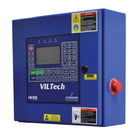
Pre-Startup Check List
Pre-Wired done at factory. The necessary field wiring connections are described below.
1. Connect power (L1) to e-stop at terminal #2. Then neutral is connected on TB5 to the
middle terminal labeled “N”. Last connect ground on TB5 at the right end terminal
labeled “G”.
2. Connect the Compressor Motor to Channel 1, the hot lead connects to terminal 4 and
the neutral end to terminal 1.
3. Connect the Motor Starter AUX to Channel 9. The hot side of the dry contact to
terminal 34. The neutral side of the dry contact to terminal 35.
4. At this time connect AUX #1, AUX #2, Remote Start/Stop, or water solenoid that
may have shipped loose per the wiring diagram.
5. First, press “Menu” key then press “#1” then next press “clear” now enter the pass-
word “999999”. Then enter setpoints by pushing “SETPT” key then #2 for Setpoints.
Now go through each screen for 1.Pressure, 2.Temperature, and 3.Capacity. Use the
“QUIT” or “SAVE” button to go to previous screen.
6. Still under “Setpt” screen setup Capactiy Control by pressing #4 and Misc Control by
pressing #5. If multiple control setpoints are going to be used then setup a Schedule by
pressing #3, please read the manual for more information.
7. Now press the “Menu” button then press #4 “System Setup” then #5 “Configure
Hardware” then #4 “Staging Configuration”, now on this screen please make sure that
the correct steps of unloading are shown on the right side of the screen, if the steps are
not correct then look in the manual or call Electrical Engineering at Vilter Manufactur-
ing LLC. Now to get out of this screen press “Quit” key if no changes were done
otherwise press “Save” to get to the previous screen.
8. Next press #5 “Control Configuration” and verify the refrigerant and enable/disable
any options that are needed or not.