144
Hardware Interface Description
Hardware Requirements
The Vilter 400 Series Compressor uses the on-board COMM 1 port for Modbus RTU communications. The hard-
ware configuration for both protocols is 5-volt RS-485 or RS422 multi-drop.
Interface Connections
Physical interface connections for Modbus communications are made at COMM 1 located on the left side of the
main microprocessor board next to the corner. The following table shows the pin-outs for the Viltech hardware for
COMM 1.
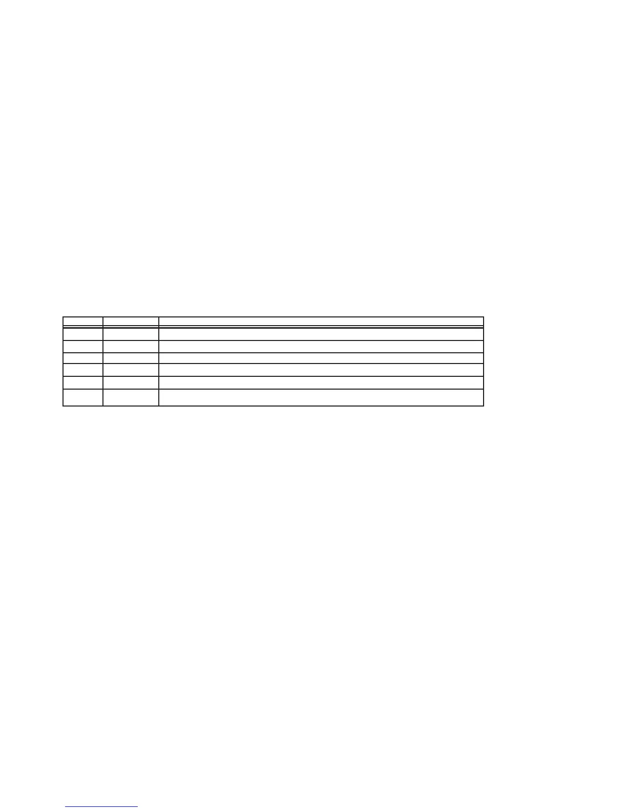
Pin Name Function
1 TX+ Transmit Data (Positive)
2 TX- Transmit Data (Negative)
3 GND Ground
4 GND Ground
5 RX- Receive Data (Negative)
6 RX+ Receive Data (Positive)
NOTE: For RS-485 communications, use Terminals 1 and 2 for the network connection and add a
jumper between Terminals 1-6 and 2-5.
The use of low capacitance twisted/shielded cable is required (e.g. Belden #9503 or eq.). The shields should be
grounded at the master computer end of the cable and floated at the microprocessor end.
Figure 1 shows the interface cabling connections for typical Modbus applications. Also shown are the
recommended shield grounding requirements for an in-line data path and a split data path. Other
controllers or PC configurations may be different.
NOTE: Since Modbus communications share a port with Viltech communications, The port must be
selected for Modbus operation on the Communications Setup screen.