6
Shield
+
_
TX
3
1
11
7
A.3) LINEAR INPUTA.3) LINEAR INPUT
A.3) LINEAR INPUTA.3) LINEAR INPUT
A.3) LINEAR INPUT
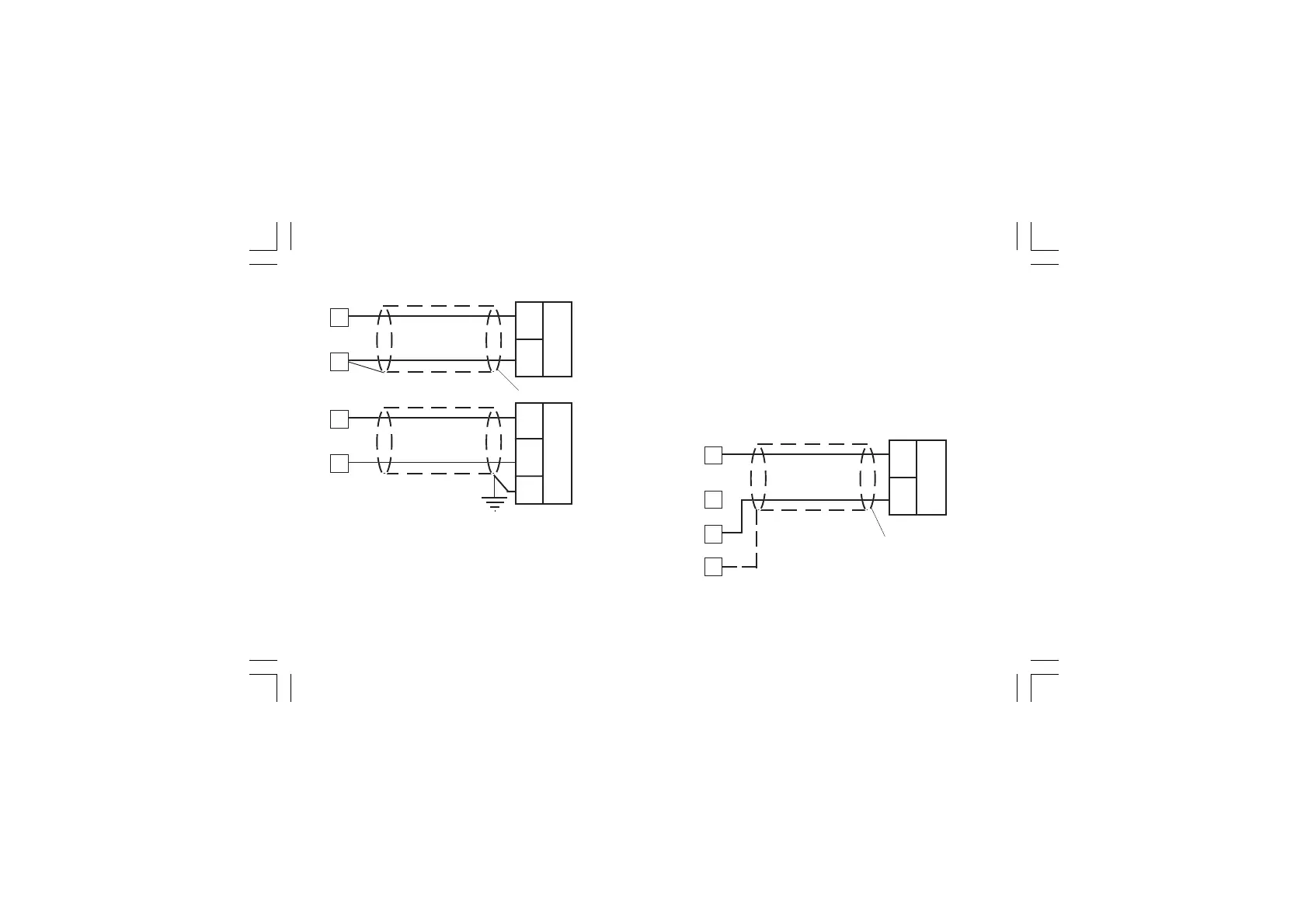
Fig. 6 mA, mV AND V INPUTS WIRING
NOTESNOTES
NOTESNOTES
NOTES:
1) Don’t run input wires together with power cables.
2) Pay attention to the line resistance; a high line resistance
may cause measurement errors.
3) When shielded cable is used, it should be grounded at one
side only to avoid ground loop currents.
4) The input impedance is equal to:
< 5 Ω for 20 mA input
> 1 MΩ for 60 mV input
> 200 kΩ for 5 V input
> 400 kΩ for 10 V input
A.4) 2, 3 AND 4-WIRE TRANSMITTER INPUTA.4) 2, 3 AND 4-WIRE TRANSMITTER INPUT
A.4) 2, 3 AND 4-WIRE TRANSMITTER INPUTA.4) 2, 3 AND 4-WIRE TRANSMITTER INPUT
A.4) 2, 3 AND 4-WIRE TRANSMITTER INPUT
Fig. 7.A INPUTS WIRING FOR 2-WIRE TRANSMITTER
Shield
_
+
mA,
mV
or
V
3
1
+
_
G
mA
mV
or
V
1
3
XKP-1-D1.pmd 25/05/2006, 11.286
 Loading...