18
6) For 24 V DC the polarity is a not care condition.
7) The power supply input is fuse protected by a sub miniature
fuse rated T, 1A, 250 V.
When fuse is damaged, it is advisable to verify the power supply
circuit, so that it is necessary to send back the instrument to
your supplier.
8) The safety requirements for Permanently Connected
Equipment say:
- a switch or circuit-breaker shall be included in the building
installation;
- it shall be in close proximity to the equipment and within
easy reach of the operator;
- it shall be marked as the disconnecting device for the
equipment.
NOTENOTE
NOTENOTE
NOTE: a single switch or circuit-breaker can drive more than
one instrument.
9) When a neutral line is present please connect it to the 32
terminal.
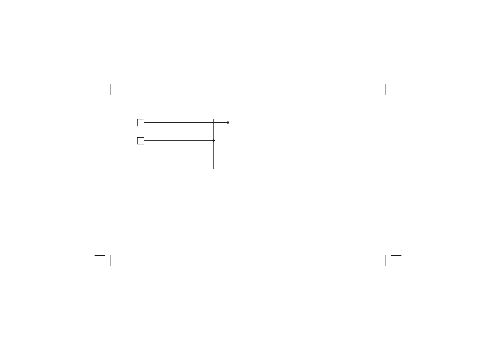
G) POWER LINE WIRINGG) POWER LINE WIRING
G) POWER LINE WIRINGG) POWER LINE WIRING
G) POWER LINE WIRING
Fig. 18 POWER LINE WIRING
NOTESNOTES
NOTESNOTES
NOTES:
1) Before connecting the instrument to the power line, make sure
that line voltage corresponds to the description on the identifi-
cation label.
2) To avoid electrical shock, connect power line at the end of the
wiring procedure.
3) For supply connections use No 16 AWG or larger wires rated for
at last 75 °C.
4) Use copper conductors only.
5) Don’t run input wires together with power cables.
33
L (L1)
Neutral
32
N (L2)
POWER LINE 100 V to
240 V A.C (50/60Hz)
or 24 V AC/DC
Line
XKP-1-D1.pmd 25/05/2006, 11.2818