8
B) AUXILIARY INPUTB) AUXILIARY INPUT
B) AUXILIARY INPUTB) AUXILIARY INPUT
B) AUXILIARY INPUT
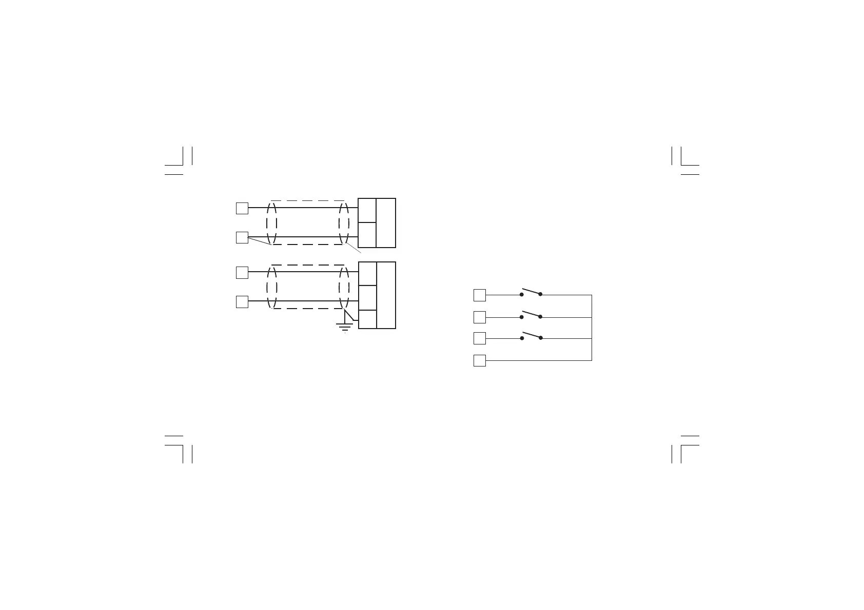
Fig. 8 AUXILIARY INPUT WIRING
NOTESNOTES
NOTESNOTES
NOTES:
1) This input is
not isolated not isolated
not isolated not isolated
not isolated from measuring input. A double or
reinforced insulation between instrument output and power
supply must be assured by the external instrument.
2) Don’t run input wires together with power cables.
3) Pay attention to the line resistance; a high line resistance
may cause measurement errors.
8
9
10
11
DIG. 1
DIG. 2
DIG. 3
Shield
_
+
mA
or
V
6
5
+
_
G
mA
or
V
5
6
4) When shielded cable is used, it should be grounded at one
side only to avoid ground loop currents.
5) The input impedance is equal to:
< 5 Ω for 20 mA input
> 200 kΩ for 5 V input
> 400 kΩ for 10 V input
C) LOGIC INPUTSC) LOGIC INPUTS
C) LOGIC INPUTSC) LOGIC INPUTS
C) LOGIC INPUTS
Fig. 9.A - LOGIC INPUTS DIG 1, 2, 3 WIRING
XKP-1-D1.pmd 25/05/2006, 11.288