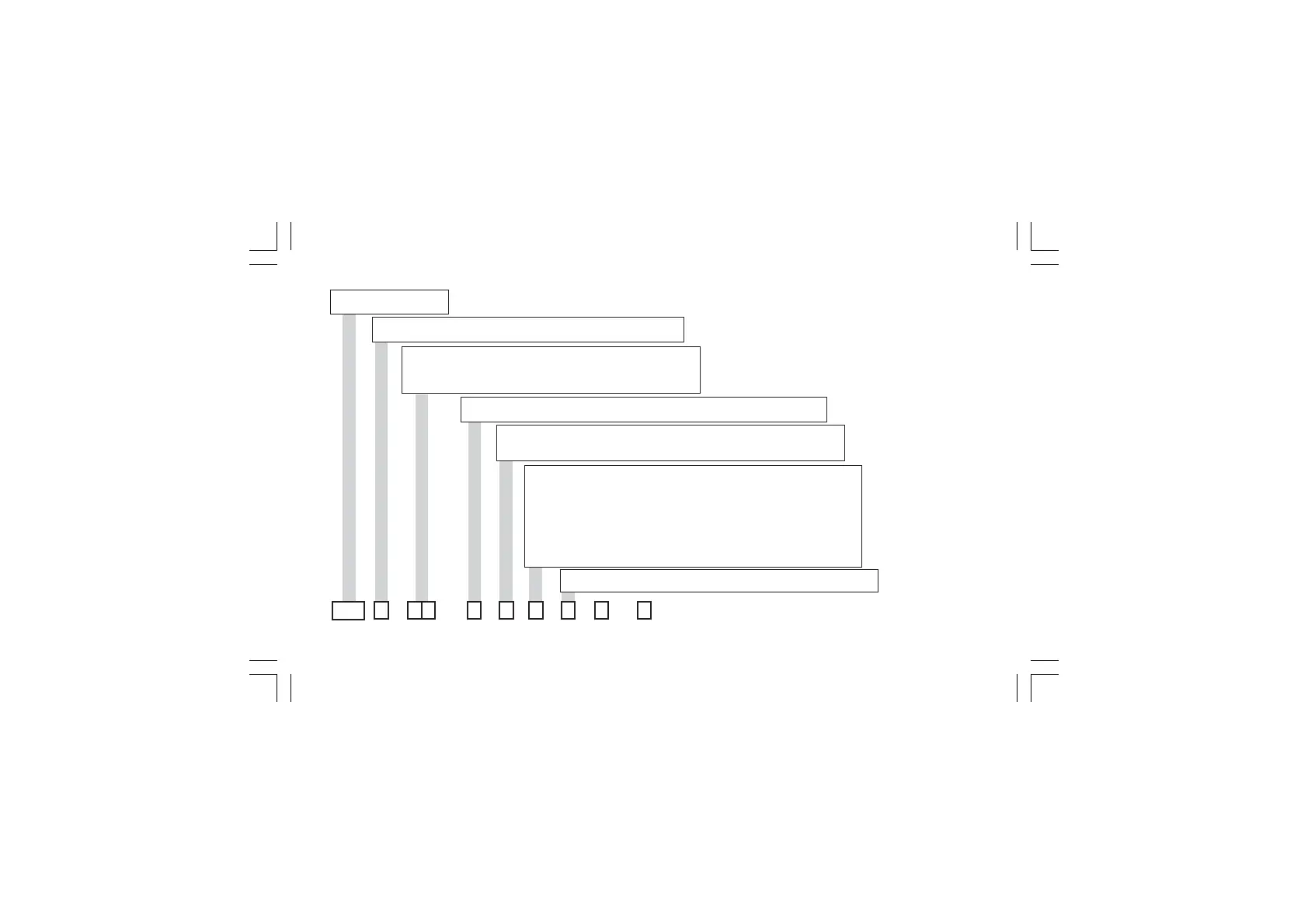
A. 15
* For MKP only
CODINGCODING
CODINGCODING
CODING
MODEL:MODEL:
MODEL:MODEL:
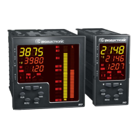
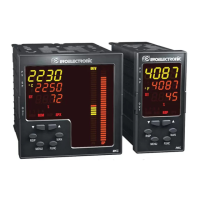
MODEL: MKP = 1/4 DIN
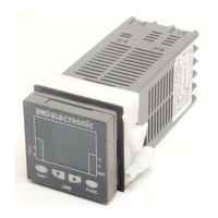
PKP = 1/8 DIN
INPUTINPUT
INPUTINPUT
INPUT
: :
: :
: 1 = Main + Aux-in + Logic Inputs
6 = Main + Aux-in + Logic Inputs +OFD (or Feedback selectable)
OUT1 and OUT2:OUT1 and OUT2:
OUT1 and OUT2:OUT1 and OUT2:
OUT1 and OUT2:11 = Two relay outputs
44 = Two TRIAC outputs
61 = One SSR + one relay output
66 = Two SSR outputs
OUT3 and OUT4:OUT3 and OUT4:
OUT3 and OUT4:OUT3 and OUT4:
OUT3 and OUT4:1 = Two relay outputs
2 = Two relay outputs interlockable by jumper (for servomotor output)
OUT5 and OUT6:OUT5 and OUT6:
OUT5 and OUT6:OUT5 and OUT6:
OUT5 and OUT6:0 = Not provided
5 = Two mA outputs
7 = One mA output (Out 5)
OPTIONS: OPTIONS:
OPTIONS: OPTIONS:
OPTIONS: 0 = Not provided
1 = Aux. PWS
2 = RS485 + Aux. PWS
4 = Clock calendar + RS485 + Aux. PWS
5 = Clock calendar + Aux. PWS
6*= RS485 + Aux. PWS + 4 Log. in + 5 Digital out.
7*= RS485 + Aux. PWS + 8 Log. in + 10 Digital out.
8*= Clock calendar + RS485 + Aux. PWS + 4 Log. in + 5 Digital out.
9*= Clock calendar + RS485 + Aux. PWS + 8 Log. in + 10 Digital out.
POWER SUPPLPOWER SUPPL
POWER SUPPLPOWER SUPPL
POWER SUPPL
YY
YY
Y
::
::
:3 = 100/240V AC
5 = 24V AC/DC
0
0
xkp-a-D1.pmd 25/05/2006, 11.2915