9
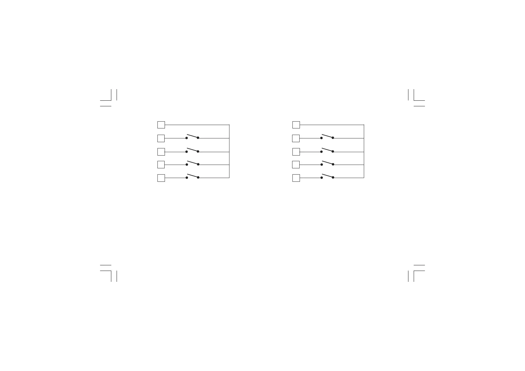
Fig. 9.B - LOGIC INPUTS IN 1, 2, 3 and 4 WIRING
58
59
IN 2
IN 3
56
57
IN 1
60
IN 4
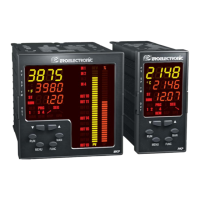
Fig. 9.C - LOGIC INPUTS IN 5, 6, 7 and 8 WIRING
NOTESNOTES
NOTESNOTES
NOTES:
1) Do not run logic input wiring together with power cables.
2) Use an external dry contact capable of switching 0.5 mA,
5 V DC.
3) The instrument needs 110 ms to recognize a contact status
variation.
4) The logic inputs are
NOT NOT
NOT NOT
NOT isolated by the measuring input.
A double or reinforced insulation between instrument input
and power line must be assured by the external element.
58
59
IN 6
IN 7
56
57
IN 5
60
IN 8
XKP-1-D1.pmd 25/05/2006, 11.289