5
A.1) TC INPUTA.1) TC INPUT
A.1) TC INPUTA.1) TC INPUT
A.1) TC INPUT
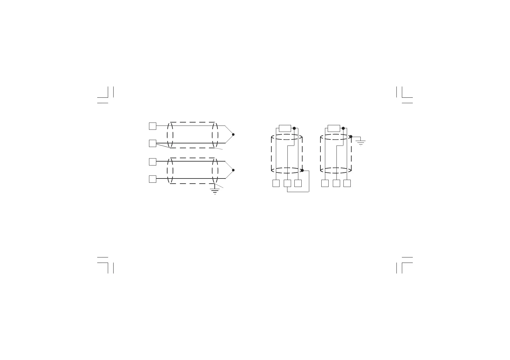
Fig. 4 THERMOCOUPLE INPUT WIRING
NOTESNOTES
NOTESNOTES
NOTES:
1) Don’t run input wires together with power cables.
2) For TC wiring use proper compensating cable preferable
shielded.
3) When a shielded cable is used, it should be connected at
one point only.
3
+
_
Shield
1
3
+
_
Shield
1
4
RTD
1
3 4
RTD
1
3
A.2) RTD INPUTA.2) RTD INPUT
A.2) RTD INPUTA.2) RTD INPUT
A.2) RTD INPUT
Fig. 5 RTD INPUT WIRING
NOTESNOTES
NOTESNOTES
NOTES:
1) Don’t run input wires together with power cables.
2) Pay attention to the line resistance; a high line resistance
may cause measurement errors.
3) When shielded cable is used, it should be grounded at one
side only to avoid ground loop currents.
4) The resistance of the 3 wires must be the same.
XKP-1-D1.pmd 25/05/2006, 11.285