4
Connections are to be made with the instrument
housing installed in its proper location.
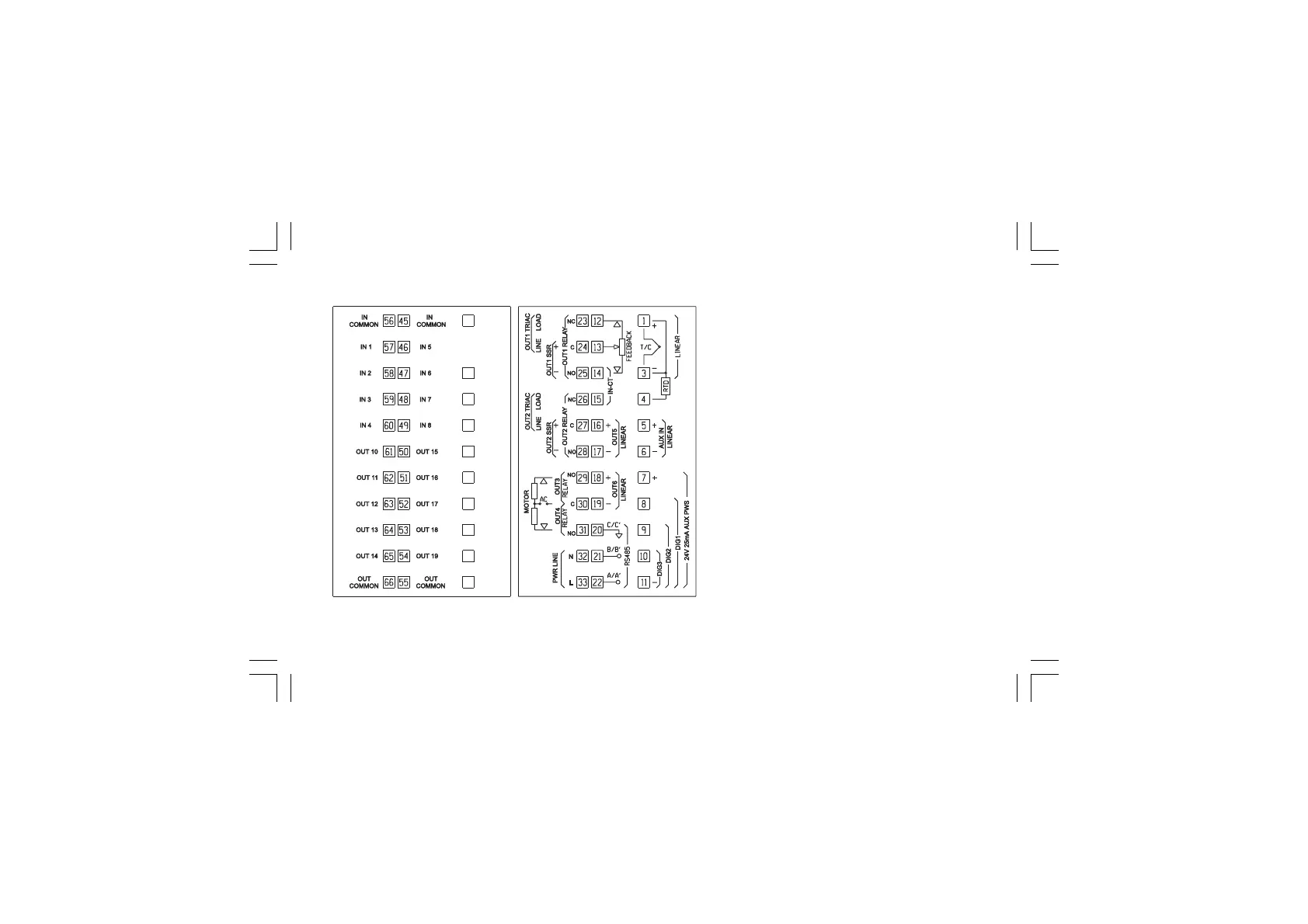
A) MEASURING INPUTSA) MEASURING INPUTS
A) MEASURING INPUTSA) MEASURING INPUTS
A) MEASURING INPUTS
NOTENOTE
NOTENOTE
NOTE: Any external component (like zener
barriers etc.) connected between sensor and input
terminals may cause errors in measurement due to
excessive and/or not balanced line resistance or
possible leakage currents.
CONNECTION DIAGRAMSCONNECTION DIAGRAMS
CONNECTION DIAGRAMSCONNECTION DIAGRAMS
CONNECTION DIAGRAMS
Fig. 3 REAR TERMINAL BLOCK
XKP-1-D1.pmd 25/05/2006, 11.284