132
DISPLAY FUNCTION DURING CONTROLLER MODEDISPLAY FUNCTION DURING CONTROLLER MODE
DISPLAY FUNCTION DURING CONTROLLER MODEDISPLAY FUNCTION DURING CONTROLLER MODE
DISPLAY FUNCTION DURING CONTROLLER MODE
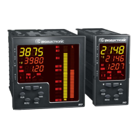
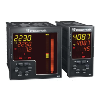
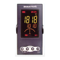
When device is powered and it is operating in automatic mode,
the upper display shows the process variable and the middle
display shows the set point value (final or operative according
to “SP.dS” [C.I07] parameter setting).
NOTENOTE
NOTENOTE
NOTE: when the auxiliary input is used, the set point value
shown by the instrument is equal SP parameter value plus the
values measured by the auxiliary input (Trim function).
We define the above condition as “normal display mode”.
The lower display will show:
a) at instrument start up, the control output value (the % LED is
lighted).
NOTESNOTES
NOTESNOTES
NOTES:
In accordance with the configured output type, the control
output can be displayed in the following ways:
a.1) If the device is configured with servomotor control drive
only, the feedback position value is displayed in the
range -19.0 % to 120.0 % (the display is blank if open
loop servomotor without valve position indication has
been programmed)
a.2) If the device is configured with one control output (linear
or time proportional), the control output value is
displayed in the range 0 % to 100 %.
a.3) if the device is configured with two control outputs the
value of the MAIN output is shown on the two most
significant digits while the value of the SECONDARY
output is shown on the two less significant digits.
The decimal point between the two values will be
flashing.
NOTENOTE
NOTENOTE
NOTE: the graphic symbol “ “ shows that the
specific control output is > 100%.
Whenever one of the two outputs is a servomotor type,
the instrument shows, for this output, the feedback
position (in the range from -19 % to 99 %) instead of the
output in percent.
b)push the FUNC push-button; the lower display will show
" A." followed by the current consumed by the load under
test when the load is in ON condition (see also "OUT failure
detection").
c)Push FUNC push-button again, the lower display will show
" b." followed by the leakage current running in the load
under test when the load is in OFF condition (see also "OUT
failure detection").
d)Push FUNC push-button again, the lower display will show
" Fd." followed by the OUT failure detection alarm status:
OF = no alarm
AL (flashing) = alarm
AL (steady) = acknowledged alarm
e)Push FUNC push-button again, the lower display will show
" ñ." followed by the MAIN control output value in the range
XKP-1-D1.pmd 25/05/2006, 11.28132