42
CnF. 3CnF. 3
CnF. 3CnF. 3
CnF. 3
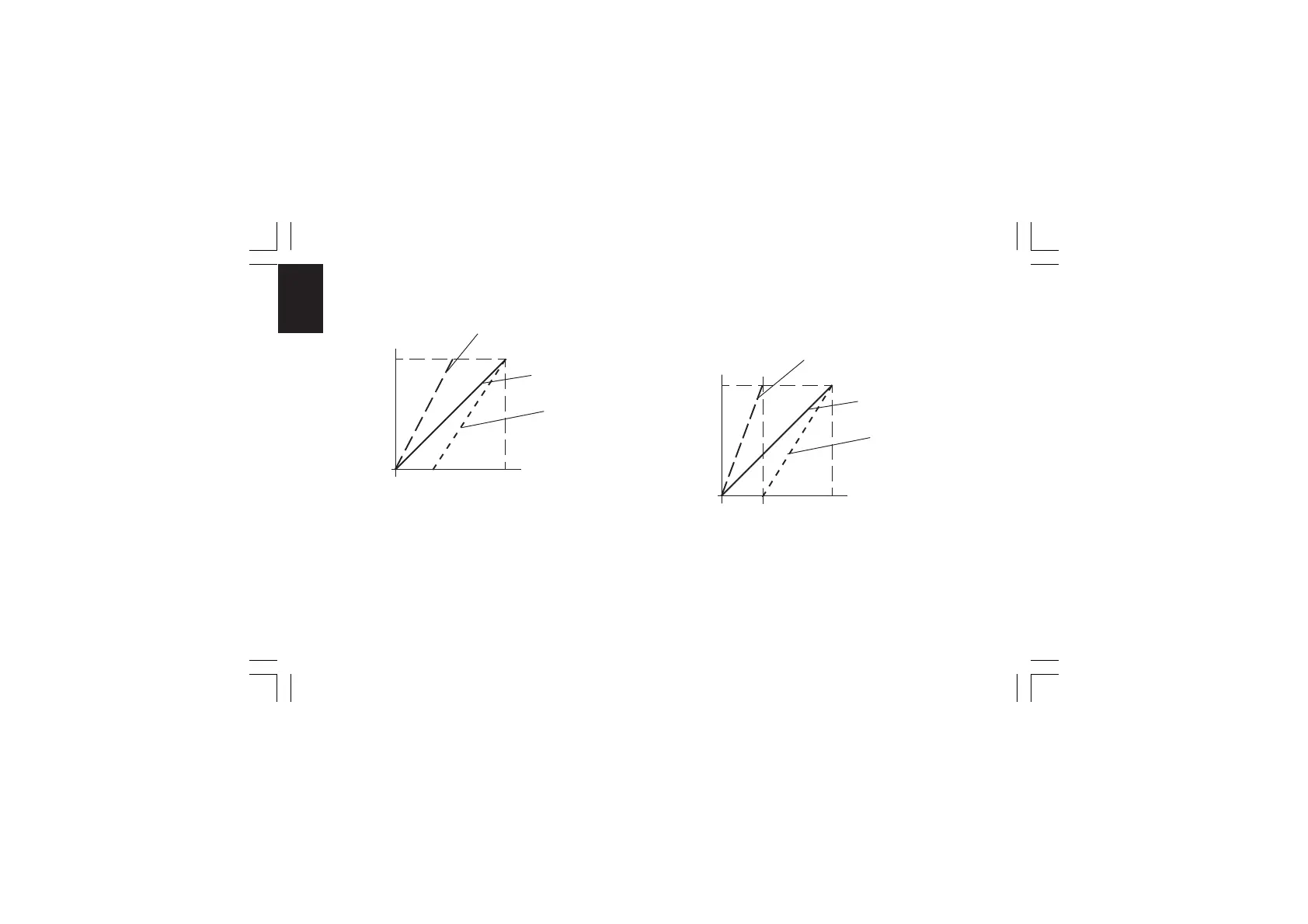
The relation between the Calculated Power Output and the
resulting real outputs are shown below:
where:
- for the first split output (MAIN)
Bias 1 = -A
Gain 1 = 100 / (B - A)
- For the second split output (SECONDARY)
Bias 2 = -C
Gain 2 = 100 / (D - C)
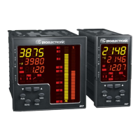
FOR EXAMPLEFOR EXAMPLE
FOR EXAMPLEFOR EXAMPLE
FOR EXAMPLE:
Let's suppose that the first split output operates from 0 % to
33.3 % of the calculated output while the second one operates
from 33.3 % to the 100 % of the calculated output.
Where: A = 0 %
B = C = 33.3 %
D = 100 %
ABCD
0 %
100 %
100 %
Calculated
PWR Output
Real PWR
Output
First split
output (MAIN)
Standard curve
Second split
output
(Secondary)
33.3 %
0 %
100 %
100 %
Calculated
PWR Output
Real PWR
Output
First split
output (MAIN)
Standard curve
Second split
output
(Secondary)
A
B e C
D
XKP-1-D1.pmd 25/05/2006, 11.2842