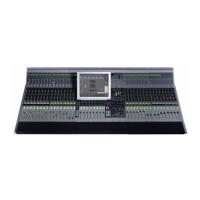
Euphonix Max Air Mixing Console Operation Manual
xiv
4-26 *Knobset View .................................................................................................................70
4-27 Mixer Model View ............................................................................................................71
4-28 Preferences View ..............................................................................................................72
4-29 Channels Tabs ...................................................................................................................74
4-30 Assign View ......................................................................................................................74
4-31 Spill Area function ............................................................................................................76
4-32 Lock Strips View ..............................................................................................................77
4-33 Fader Unity popup ............................................................................................................77
4-34 Status View .......................................................................................................................78
4-35 Super Channel View .........................................................................................................79
4-36 Channel Selector Popup ....................................................................................................80
4-37 Process Order Popup .........................................................................................................80
4-38 Channel Routing Popup ....................................................................................................81
4-39 Meters-Presets Popup .......................................................................................................82
4-40 Meters-Screen Popup with Meters Display ......................................................................83
4-41 Meters-Fader Popup ..........................................................................................................84
4-42 Meters-Setup View ...........................................................................................................85
5-1 Console Strip and Bus display with block diagrams for Main and Swap channels ..........88
5-2 Channel Assign View .......................................................................................................89
5-3 Channel Selector ...............................................................................................................91
5-4 Main and Swap Channel displays .....................................................................................91
5-5 Strip Fader .........................................................................................................................92
5-6 Rotary Knob Controls .......................................................................................................95
5-7 Strip Function Switches ....................................................................................................95
5-8 Mono Input knobsets ........................................................................................................96
5-9 Stereo Input Knobsets .......................................................................................................98
5-10 Dynamics knobsets ...........................................................................................................98
5-11 EQ knobsets ......................................................................................................................99
5-12 Filters knobsets ...............................................................................................................100
5-13 Pan Knobsets ...................................................................................................................102
5-14 Aux bus Knobset .............................................................................................................104
5-15 Channel processor order and patch points ......................................................................105
5-16 Group Bus Routing Knobsets .........................................................................................106

 Loading...