Euphonix Max Air Mixing Console Operation Manual Event System
182
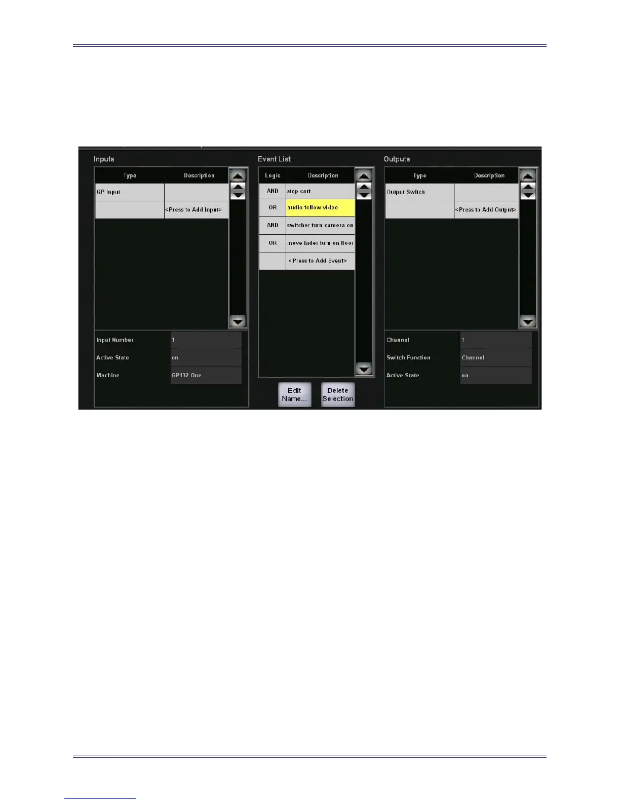
11. Touch the field next to Active State and select On from the Active State Popup.
This turns channel 1 on when camera 1 is selected by the video switcher. The
Events View should now look similar to Figure 10-15.
Figure 10-15 Input and One Output Set
12. Repeat Steps 8–11 to create additional output events to mute channels 2, 3, and
4 but set the Channel to 2, 3, and 4, respectively, and set the Active State to
Off for each.
So far, you have achieved the following functionality: When the video switcher selects
camera 1, channel 1 turns on and channels 2–4 mute.
Repeat the entire procedure with appropriate channel numbers to:
• program channel 2 to turn on when the video switcher selects camera 2 and
mute channels 1, 3, and 4.
• program channel 3 to turn on when the video switcher selects camera 3 and
mute channels 1, 2, and 4.
• program channel 4 to turn on when the video switcher selects camera 4 and
mute channels 1, 2, and 3.
Each tally input requires a discrete connection at the GP 132.