A1000 32 532210 04 - Rev.A
L/3L/3 L/3
L
11
11
Ø 7 mm
35
3 4
1 1
3 4
5
11
9
4
3
7
7
8
9
66
10
7
8
11
Nm
8
6
2.5
Nm
2
10 mm
8 mm
6 mm
Translation of the original instructions
ENGLISH
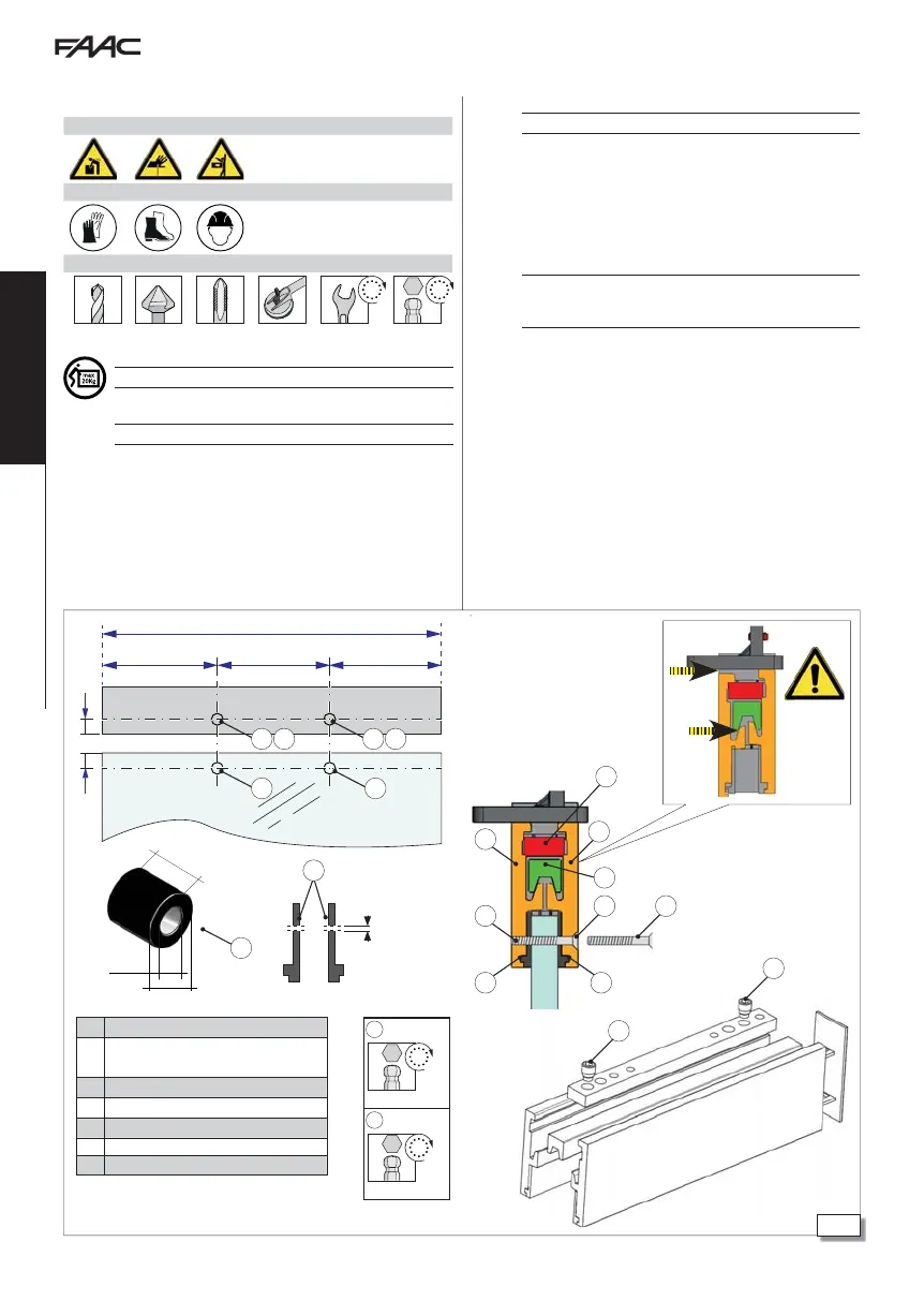
10. INSTALLING THE GLASS LEAVES
Ø 8.5 mm
bush Ø internal 6 mm
Ø external 8 mm
Ø 6.5 mm with 45° flaring
Ø 5.0 mm with M6 tapping
Ø 7.0 mm
2 x M8
2 x M6
RISKS
PERSONAL PROTECTIVE EQUIPMENT
REQUIRED TOOLS
Ø 5-6.5 mm
45° M6 8 6-8
For manual lifting, there should be 1 person for every 20 kg to be lifted.
!
Comply with the glass thickness =
10-11 mm.
1. The glass must be drilled as shown 35-
.
2. Insert a bush in each hole in the glass 35-
.
3.
Make 2 holes on the profiles of the grip
per 35-
-
.
4. Cut 2 pieces of glass beading with the length equal to L.
5. Drill holes in the seals in correspondence to the holes in the glass
35-
6.
Insert the 2 seals into the profiles 35-
.
7. Clean the glass, insert the gripper.
!
Ensure the beading is in its housing.
8. Assemble the gripper as follows: Insert elements
and
into
the 2 plates
.
9. Tighten the 2 grub screws 35-
10. Part
must be aligned with the fixing holes on the carriage
36-
11. Insert 2 galvanised countersunk head screws into the holes
35-
.
!
The glass must be fully inserted until it touches the clamps on its upper
profile. If the grip of the clamp on the glass is not correct, the glass might
fall. The two clamp profiles must be aligned.
Install each leaf as described below.
12. Adjust the counter wheel to prevent the carriage from falling.
13. Place the lower plate onto the glass leaf.
- Keep to the measurements indicated in diagrams :
- 94 - 105 for RIGHT single leaf automations
- 95- 106 for LEFT single leaf automations
- 96 - 107 for DOUBLE leaf automations.
14. Fasten the lower plate onto the leaf gripper using the 2 screws
36-