A1000 45 532210 04 - Rev.A
0.0
RESET/SETUP
DL2
DL11
MAIN
F1
USB
+
-
F
ERR
BAT1
OPEN
EMERG
BAT2
SIC
_
OP
SIC
_
CL
J10
J14
J11
J12
J13
V G
S1
G
T
J1
J17
V RX TX G
J8
E1 G E2
J7
T1 G
T2
R1
G R2
J9
V G 01 02 02
J22
J21
V
G
I1
I2
G
I3
I4
V
J18
G CH CL G
J23J24
J25
V G
S2
G
T
J2
57
DL3
DL6
DL8
DL10
DL7
DL9
DL2
DL5
DL1
DL11
DL4
Translation of the original instructions
ENGLISH
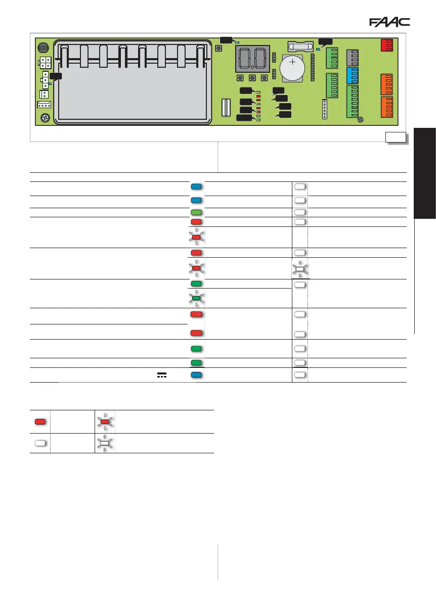
Name Description Statuses
DL1 main
(BLUE) MAIN: power supply unit input * main power supply ON main power supply OFF
DL2
(BLUE) +5V: board power * present absent
DL3
(GREEN) USB: storage device device present * device absent
DL4
RED
ERR: Error/Alert in progress
error * no error/alert
indication
DL5
RED BATT1: battery status
battery discharged * battery charged
battery use
battery discharged with no mains power
supply
DL6
(GREEN) BATT2: battery charger status
battery charger at rest
battery charger not working due to mains
power down or fault
battery charger working
DL7
RED SIC_OP: safety on opening
input active (sensors busy) * input not active (sensors not busy)
DL8
RED SIC_CL: safety on closing
DL9
(GREEN) EMERG: emergency
input active
(door opened in emergency)
* input not active
DL10
(GREEN) OPEN: open button input active (Open impulse) * input not active
DL11
(BLUE)
VACC: accessories power (+ 24V ) * present absent
LED statuses:
on flashing * = standby condition
off in sleep mode: off with blinking every 5 s
10 LEDs on the board