A1000 47 532210 04 - Rev.A
Translation of the original instructions
ENGLISH
J11 MOTOR
J11
M1 Motor connection
J12 MOTOR ENCODER
J12
M1 Motor encoder connection
J13 XB LOCK/ XM LOCK MOTOR BLOCK AND
MONITORING OPTIONAL
J13
Connection for XB LOCK /XM LOCK motor block with monitoring
(OPTIONAL)
J14 EMERGENCY BATTERY
The board maintains battery charge, but does not charge batteries when
discharged.
To check the charge status see LEDs DL5 and DL6 (45).
J14
Emergency battery connection
J17 USB PORT
J17
Connection of the USB memory device
J18 INTERCOM
J18
G CH CL G
G GND Accessories power supply negative and Common contacts
CH CH CANBUS High Channel
CL CL CANBUS Low Channel
G GND Accessories power supply negative and Common contacts
J21 INPUTS I1I2I3I4
V
G
I1
I2
G
I3
I4
V
J21
V
+24V
accessories power supply
I4 Configurable input I4
I3 Configurable input I3
G GND Accessories power supply negative and Common contacts
I2 Configurable input I2
I1 Configurable input I1
G GND Accessories power supply negative and Common contacts
V
+24V
accessories power supply
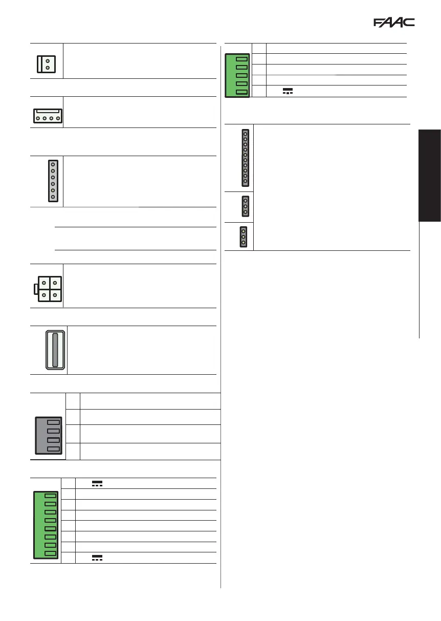
J22 CONFIGURABLE OUTPUTS
V G 01 02 02
J22
O2 Output2 NC/NO configurable relay output (programming)
O2 Output2 NC/NO configurable relay output (programming)
O1 Output1 configurable (programming)
G GND Accessories power supply negative and Common contacts
V
+24V
accessories power supply
J23 J24 J25 OPTIONAL MODULES
J23
Module connection
G-COM / WI-COM / Net-COM
J24
J25