A1000 52 532210 04 - Rev.A
TX1
RX1
T1 G
T2
R1
G R2
TX2
RX2
TX1
RX1
T1 G
T2
R1
G R2
66
67
+ RX2
GND
+ RX1
+ TX2
GND
+ TX1
J9
+ R2
GND
+ R1
+ T2
GND
+ T1
69
+24V
V G 01 02 02
J22
J7
68
J7
E1 G E2
E1 G E2
Translation of the original instructions
ENGLISH
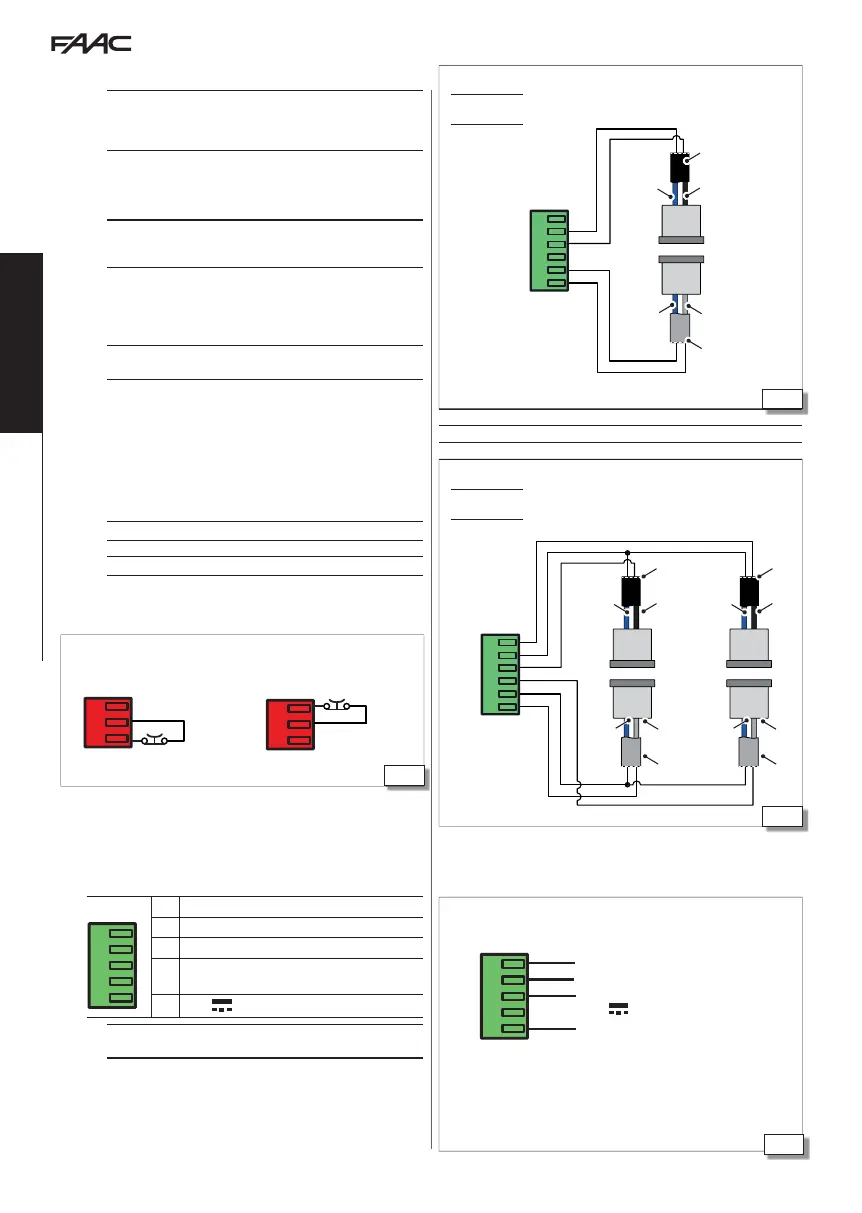
12.8 J9 XFA BUTTON PHOTOCELLS
!
Photocells are not permitted as safety devices in European Community
countries in which the EN 16005:2012 standard is in force. Specifically,
photocells are considered as auxiliary devices, complementary to safety.
In extra-European countries where the EN 16005:2012 standard is not in
force, traditional photocells and sensors can be used.
Button photocells are constantly monitored by the door’s control electronic
board, which controls correct operation at each movement.
Connect the photocells and enable them in programming (
bP) 66
or 67.
NO PHOTOCELL - If no button photocells are used, leave the inputs of
connector J9 free and set the function
bP =
no.
12.9 J7
INPUTS E1 E2
The EMERGENCY control has priority over any other input, in any operating
condition and mode, except MANUAL operation.
An input (E1 and /or E2 recommended) configured as emergency
causes the door to OPEN / STOP/ CLOSE ,depending on how
has been programmed.
It remains active as long as the control is pressed.
1. Connect an NO or NC type contact push-button.
2. Enable input
E1 E2 and select from 30 to 35.
3. The two controls
E1and
E2 are independent.
For specific functions of the inputs see § 14.2
The NO contact can be programmed via the SDK EVO.
blueblue
blue
blue
blue
blue
blackblack
black
grey
grey
grey
black
black
black
grey
grey
grey
J9
12.10 J22 CONFIGURABLE OUTPUTS
V G 01 02 02
J22
O2 Output O2 configurable
O2 Relay Output 02 configurable
O1 Output O1 configurable
G
GND Accessories power supply negative and Common
contacts
V
+24V
accessories power supply
The operation of O1 and O2 can be programmed for NC mode using
SDK EVO
01 and 02 specifications:
- O1 Open Collector output with Max load 100mA to be connected between 01
and V.
- O2 relay contact with Max load 2A to be connected between O2 and O2.
CABLE colour
TX - transmitter grey and blue (grey sheath)
RX - receiver black and blue (black sheath)
1 pair of button photocells
bP =
1
2 pairs of button photocells
bP =
2
(NC input)
NO/NC Relay Contact
(NC input)
- O1 Open Collector output with Max load 100mA to be connected between
01 and V.
- O2 relay contact with Max load 2A to be connected between O2 and O2.