Chapter 4 Installation and Wiring
PAGE 4-44
・
・・
・
Clear the connected device receiving buffer when the control power is turned on.
(“Junk” data could be output due to ‘electrical noise’ upon power up)
・
・・
・
Data does not output from TXD if CTS input is not ON
If the CTS is OFF, the fastening data is saved in the sending buffer until CTS is ON.
(Appx. 16k bytes – then overwritten)
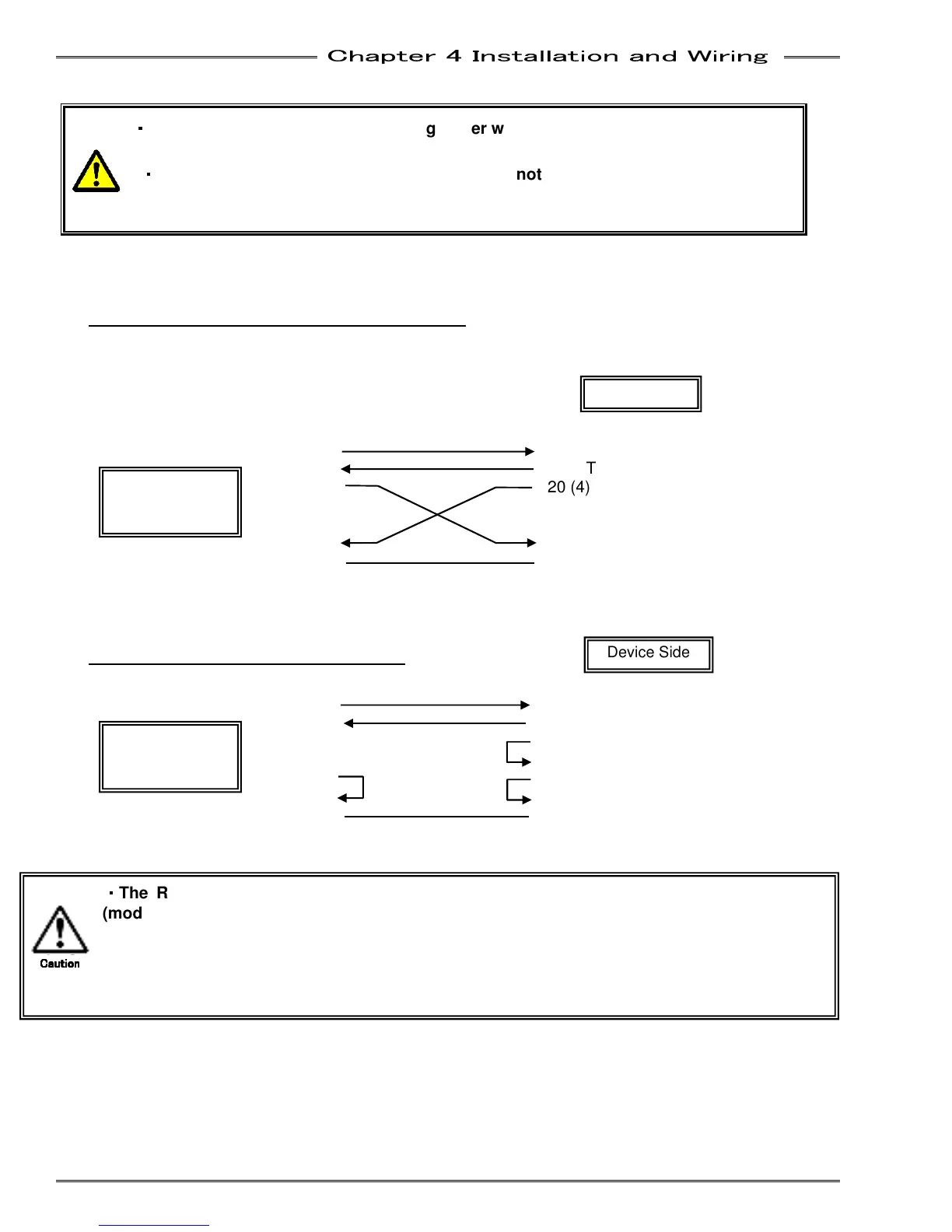
Connection diagram with hardware handshaking
(This is a standard “Null Modem” Cable configuration)
D-SUB 9 pin Female D-SUB 25 Pin Male (9 Pin Female)
TXD 3
3 (2) RXD (Result data output)
RXD 2
2 (3) TXD (ID Input)
DTR 4 20 (4) DTR
6 (6) DSR
RTS 7 4 (7) RTS
CTS
8 5 (8) CTS
GND 5 7 (5) GND
Connection diagram with data “dump” -
D-SUB 9 Female Pins D-SUB 25 Male Pins (9Female Pins)
TXD 3
3 (2) RXD (Result data output)
RXD 2 2 (3) TXD (RS232C-2 only)
DTR 4 20 (4) DTR
6 (6) DSR
RTS
7 4 (7) RTS
CTS
8 5 (8) CTS
GND 5 7(5) GND
MFC-S024
MFC-S060
MFC-S120
Device Side
MFC-S024
MFC-S060
MFC-S120
Device Side
・
・・
・
The RS232C on the MFC Unit front panel is for data output only. The Expansion Unit
(model: MFC-CF) has (2) additional RS232C ports.
RS232C-2 is for DATA INPUT only (For Part ID Data marriage to Fastening Data)
RS232C-3 is for Fastening Result DATA Output: Programmable Format (using AFC3000 S/W)
Note: This port may also be used for Controller Firmware updates (FEC use only)
Caution
CautionCaution
Caution