Chapter 3 System Description
PAGE 3-5
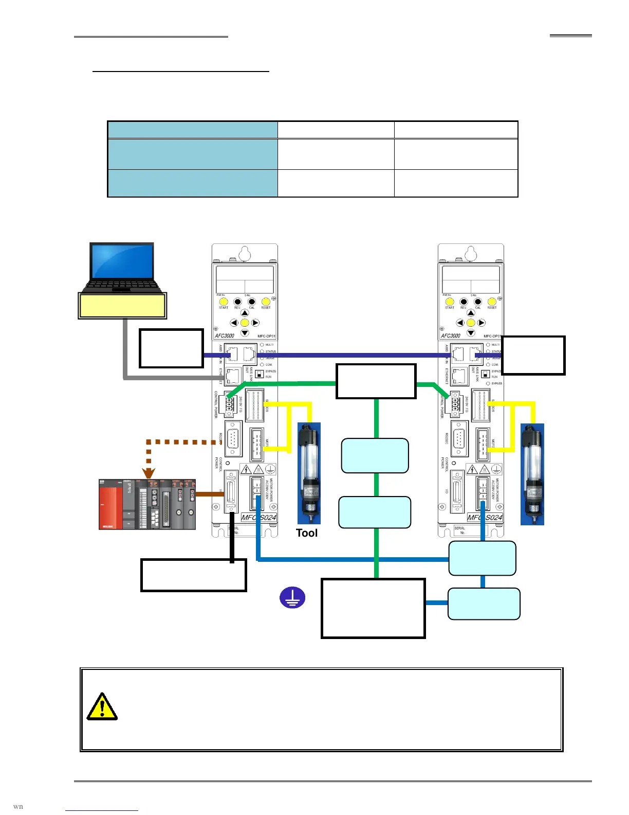
3-1-2 Multi System Diagrams
A Controller setup as a Master, will control the I/O of any slave controllers connected to it (via the AXIS
IN / OUT connection points) This configuration is referred to as a “Multi System”.
Unit Setting MASTER Spdl. No. 1 SLAVE Spdl. No. 2
Unit Front Panel SW1: No. 8
Communication axis setting
ON OFF
System Parameter D-No.
SYS-003 System Indication
Multi Multi
*
The LAN cables, circuit protectors, and noise filters are not included with the
equipment.
* Noise Filters are required where input power source is known to have electrical
“Noise”
Source
200 to 230V AC
50/60Hz
Console
Unit No. 1
Unit No. 2
Axis Link
Terminator
Axis Link
Terminator
Source 24V DC
Noise
Filter
Noise
Filter
Circuit
Protector
Circuit
Protector
Emergency Stop
Grounding
LAN Connector
Standard I/O, PLC