Chapter 3 System Description
PAGE 3-4
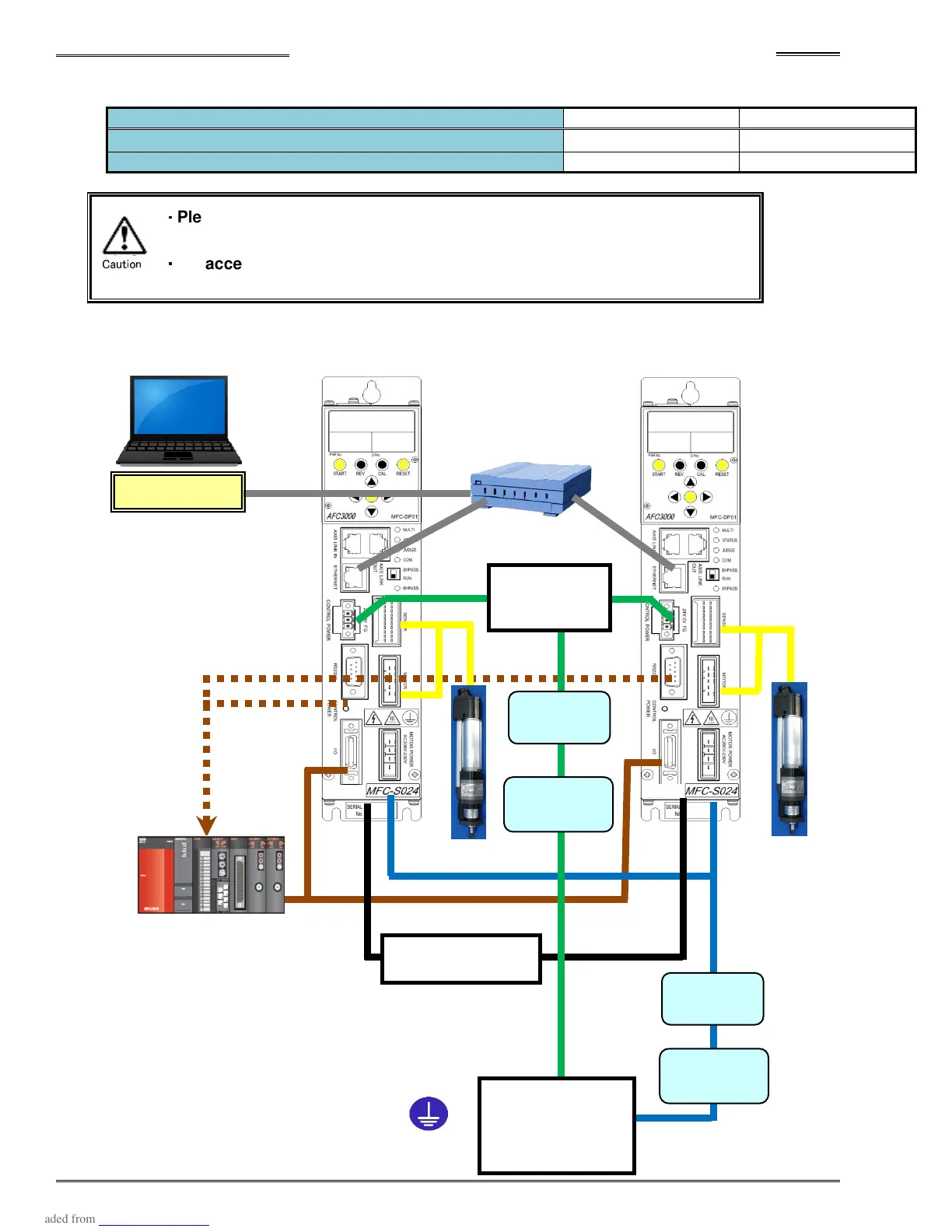
The diagram below represents a single system with two MASTER Spindles.
MASTER Spdl. No. 1
MASTER Spdl. No. 2
Unit Front Panel SW1: No. 8 Communication axis setting
ON ON
Single Single
・
・・
・
Please note that multiple MASTER Units cannot be accessed from a single
PC if a hub is not provided.
・
・・
・
To access multiple MASTER Units from a single PC, multiple AFC3000
User Consoles must be started up.
Hub
Console
Unit No. 1
Unit No. 2
Source 24V DC
Circuit
Protector
Circuit
Protector
Noise
Filter
Noise
Filter
Emergency Stop
Source
200 to 230V AC
50/60Hz
Grounding
LAN Connector
Standard I/O, PLC
Caution