Chapter 3 System Description
PAGE 3-10
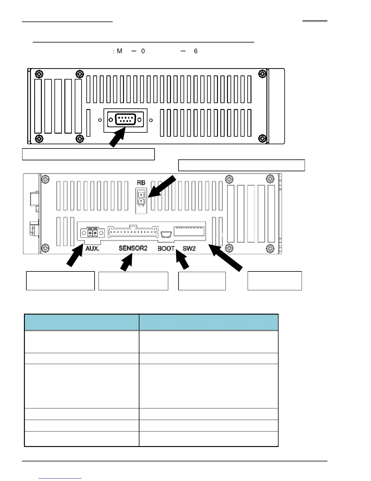
3-2-3 Controller Top & Bottom Panel Switches and Connectors
Figure below is for unit type
:
MFC
-
S024 and MFC
-
S060
Top View
Bottom View
●List of switches and connectors on the bottom side and upper panel of the controller
Item
Description
Output connector for external
monitoring
Output monitoring signals for torque analog
voltage or angle pulse
External RB connector Not used
External Emergency Stop connector
(Normally disabled - Must be enabled
using SW2 switch)
Provides hardwired STOP signal in the case
where Fieldbus is used for I/O interface. (Or
a redundant STOP signal if discrete I/O is
used) STOP signal must be ‘ON’ to Enable
System. Polarity of wiring must be followed
as shown in cable specifications 3-2-8.
External sensor input connector For Factory use
Boot connector For Factory use
Bottom panel SW2 Switch
Controller function setting switches – See
4-12-3 for setup
Output connector for external monitoring
External regeneration resistor connector
External emergency
stop connector
External encoder
input connector
Boot
connector
Bottom panel
SW2 Switch