Chapter 4 Installation and Wiring
PAGE 4-29
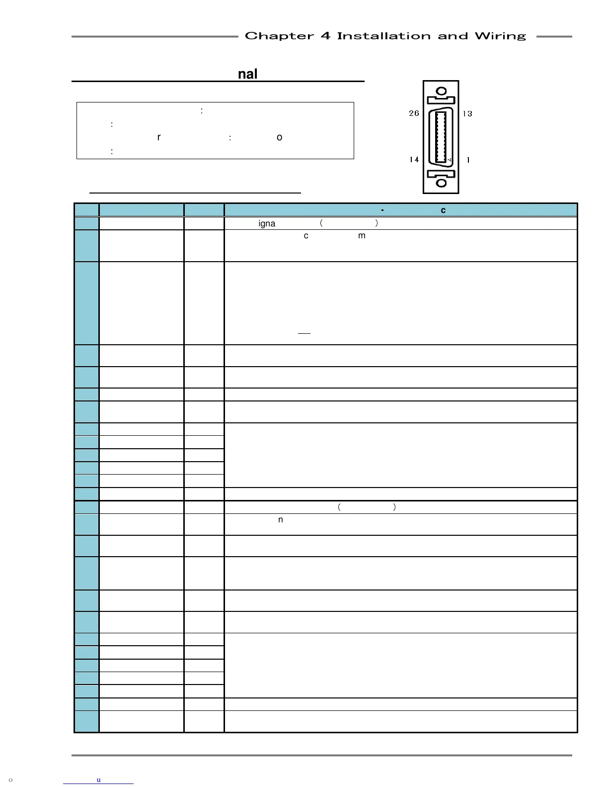
4-6 Connection of External Control Signals
4-6-1 PLC IO Signal (Single System)
IN: Input Signal
OUT: Output Signal NC: Normal Close NO: Normal Open
Pin
Signal Name IN/OUT
Function
・
・・
・
Usage Instruction
1 IN COMMON IN
Input signal common
(
Bi-directional
)
2 STOP IN NC
Signal MUST be active to perform a fastening operation.
When this signal is inactive (off), all controller operation ceases, all spindles in motion
will stop and all communication ports & input/outputs will be disabled.
3 RESET IN NO
When active (on), this signal will clear all spindle data and discrete outputs. A Zero
Check of all load transducers will be completed. During the Zero Check, the CHECK
lamp will illuminate, the READY sig
nal will turn OFF, and the ACCEPT or REJECT
lamp will light to indicate the result of the Zero Check. If the System has been disabled
by an Abnormal output, the System will not return to normal operation until the
Abnormal condition has been corrected, and
this signal has been input for
200~500ms. Do not
input this signal between cycles as part of an automatic cycle due
to the potential for spindle data loss.
4 REVERSE IN NO
The selected spindle will move in the direction opposite of the tightening directi
as long as this signal is activated (on) and maintained
5 START IN NO
The Start
input automatically resets the previous cycle, clears all data to zero, and
initiates the next fastening cycle.
6 BYPASS IN NO
Spindle is ignored as if it does not exist as long as this signal is "ON"
7 SELF CHECK OFF IN NO
When activated (ON) the Self Check of the torque transducer
performed at the start of
the fastening operation will be disabled.
8 PAR SELECT BIT 0
IN NO
These 5 inputs when selected in a binary cod
e is capable of selecting up to 32
different parameters.
9 PAR SELECT BIT 1
IN NO
10 PAR SELECT BIT 2
IN NO
11 PAR SELECT BIT 3
IN NO
12 PAR SELECT BIT 4
IN NO
13 BANK SELECT IN NO
When turned “ON” all output signals are turned OFF.
14 OUT COMMON OUT
Common Output signals
(
Bi-directional
)
15 REJECT(NG) OUT NO
Output when the fastening result is a REJECT. Indicates that the fastening operation
has fallen outside of the programmed fastening limits.
16 ACCEPT(OK) OUT NO
Output when the fastening results are an ACCEPT. Indicates the fastening operation
within the programmed fastening limits.
17 ABNORMAL OUT NO
Output when an Abnormal condition on the selected spindle
indicates that the spindle has detected an internal fault, and can no longer proceed.
18 READY OUT NO
Indicates the spindle
is ready to operate and inputs are enabled. This signal is inactive
(off) when the BUSY output is active (on).
19 BUSY OUT NO
Output after a START signal is received, and active until the fastening
complete and the READY signal is output.
20 PAR SELECT BIT 0
OUT NO
Output confirmation of PARAMETER SELECT 0~4 selections. Parameter Select bits
are active according to what parameter is set from the parameter select inputs.
21 PAR SELECT BIT 1
OUT NO
22 PAR SELECT BIT 2
OUT NO
23 PAR SELECT BIT 3
OUT NO
24 PAR SELECT BIT 4
OUT NO
25 DATA AVAILABLE OUT NO
Output when the fastening result data is available.
26 BYPASS OUT NO
Signal is active when the spindle is bypassed either from B
ypass input signal or from
the Controller’s bypass switch.
Connector on cable side
:
Sumitomo 3M Made
Type
:
10126-3000PE
Connector cover on cable side
:
Sumitomo 3M Made
Type
:
10326-52A0-008(26 position)