Chapter 4 Installation and Wiring
PAGE 4-30
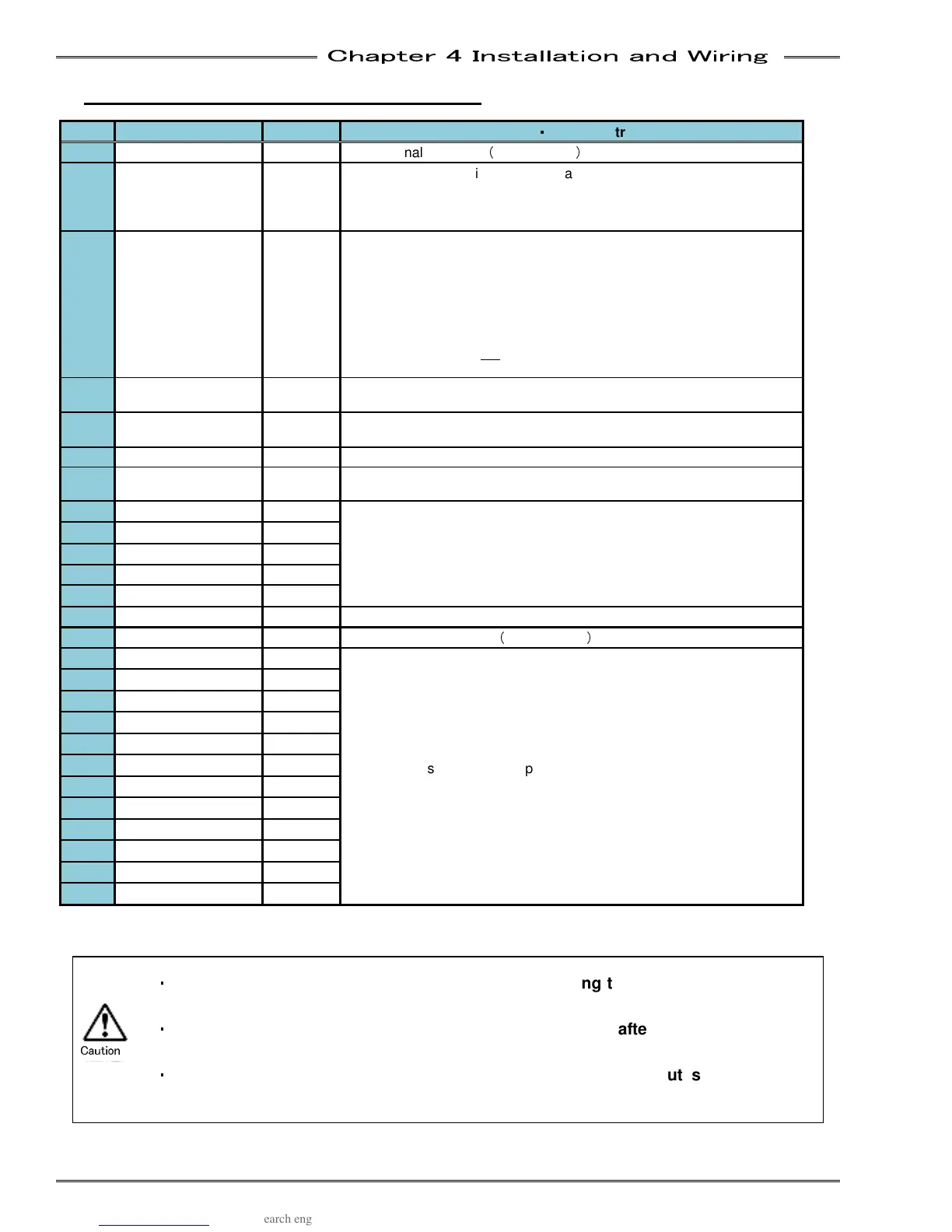
4-6-2 PLC IO Signal (Multi System:
::
:Master)
IN: Input Signal
OUT: Output Signal NC: Normal Close NO: Normal Open
Pin Signal Name IN/OUT Function
・
・・
・
Usage Instruction
1 IN COMMON IN
Input signal common
(
Bi-directional
)
2 STOP IN NC
Signal MUST be active to perform a fastening operation.
When
this signal is inactive (off), all controller operation ceases, all
spindles in motion will stop and all communication ports & input/outputs
will be disabled.
3 RESET IN NO
When active
(on), this signal will clear all spindle data and discrete
outputs. A Zero Check of all load transducers will be completed. During
the Zero Check, the CHECK lamp will illuminate, the READY signal will
turn OFF, and the A
CCEPT or REJECT lamp will light to indicate the
result of the Zero Check. If the System has been disabled by an
Abnormal output, the System will not return to normal operation until the
Abnormal condition has been corrected, and this signal has been input
for 200~500ms. Do not
input this signal between cycles as part of an
automatic cycle due to the potential for spindle data loss.
4 REVERSE IN NO
The selected
spindle will move in the direction opposite of the tightening
direction for as long as this signal is activated (on) and maintained
5 START IN NO
The Start
input automatically resets the previous cycle, clears all data to
zero, and initiates the next fastening cycle.
6 BYPASS IN NO
Spindle is ignored as if it does not exist as long as this signal is "ON"
7 SELF CHECK OFF IN NO
When activated
(ON) the Self Check of the torque transducer performed
at the start of the fastening operation will be disabled.
8
SEQ SELECT BIT 0
IN NO
These 5 inputs when selected in
a binary code is capable of selecting
up to 32 different Sequences.
9
SEQ SELECT BIT 1
IN NO
10
SEQ SELECT BIT 2
IN NO
11 SEQ SELECT BIT 3
IN NO
12 SEQ SELECT BIT 4
IN NO
13 BANK SELECT IN NO
Input bank selection (Changes definitions of output signals)
14 OUT COMMON OUT
Output signal common
(
Bi-directional
)
15 OUT DATA 0 OUT NO
Outputs the system state depending on which BANK is selected.
(See bank Output signal definition on next page)
16 OUT DATA 1 OUT NO
17 OUT DATA 2 OUT NO
18 OUT DATA 3 OUT NO
19 OUT DATA 4 OUT NO
20 OUT DATA 5 OUT NO
21 OUT DATA 6
OUT NO
22 OUT DATA 7
OUT NO
23 OUT DATA 8
OUT NO
24 OUT DATA 9
OUT NO
25 OUT DATA 10
OUT NO
26 OUT DATA 11
OUT NO
・
・・
・
Be sure to set the BANK SELECT signal to OFF during the fastening operation or
when not required
・
・・
・
Output signal OUT DATA will be output approx. 20msec after a bank select input
has changed it
・
・・
・
When bank changing is executed, the definition of the output signals will be
changed.
Caution