Chapter 4 Installation and Wiring
PAGE 4-16
4-2-3 Spindle Assemblies
Standard spindle assemblies mount inline with either a Straight Type or Offset Type tool. They are used
to “follow” the fastener as it is rundown so the fastener does not run out of the socket or bit tooling. They
are mounted to the tool mounting plate using screws. One screw thread has been provided to support
the tool during assembly/disassembly to prevent the tool from falling down when an installation screw is
fastened or loosened.
【
【【
【Caution regarding Spindle Assemblies
】
】】
】
- Select an adequate spindle assembly for the tools maximum torque.
- When installing the supporting screw, ensure that the screw does not go beyond the
thickness of the tool flange. It may cause the transducer to become less sensitive or
operate incorrectly.
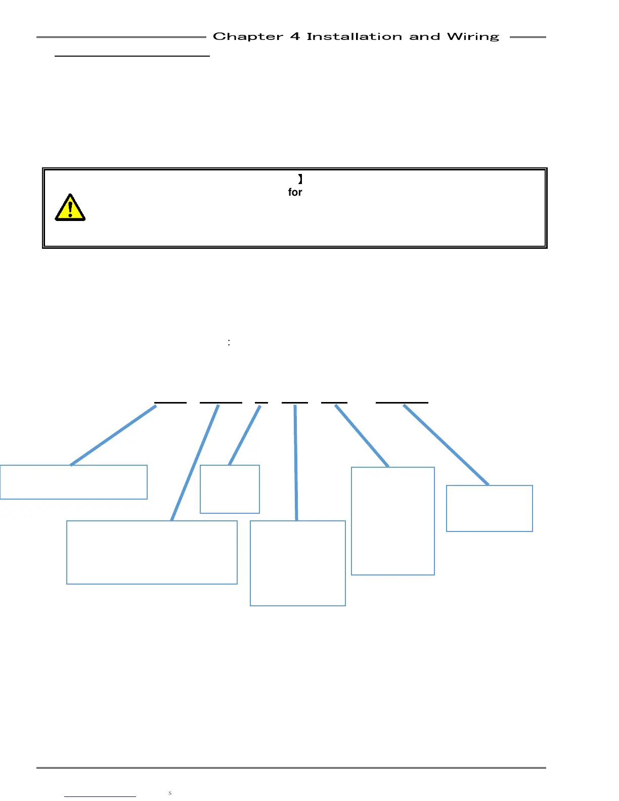
Spindle Assembly numbering convention:
SA
SASA
SA-
--
-3S1
3S13S1
3S1-
--
-2
22
2-
--
-38
3838
38-
--
-38
3838
38
x
x x
x X.XX
X.XXX.XX
X.XX
OA = OFFSET SPINDLE
LEADING “3” = 3000 SERIES
S1, S2 & S3 = NUTRUNNER MOTOR
SIZE (SEE TOOL ASSEMBLY)
FEMALE INPUT
SQUARE DRIVE
38 = 3/8
50 = 1/2
62 = 5/8
75 = 3/4
SPINDLE
STROKE
(In)
MALE OUTPUT
SQUARE
DRIVE
38 = 3/8
50 = 1/2
62 = 5/8
75 = 3/4
IF SPINDLE IS
LONGER THAN
STANDARD