Chapter 3 System Description
PAGE 3-3
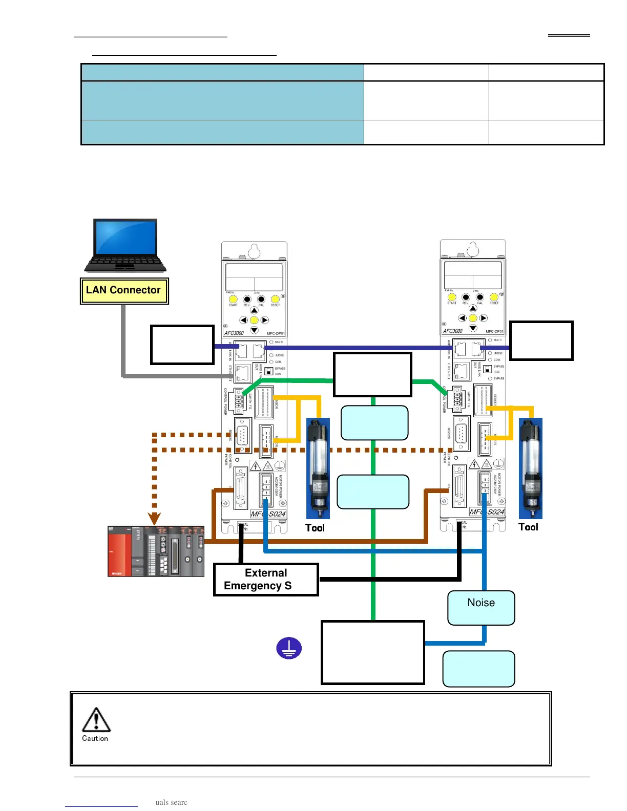
3-1-1 Single System Diagrams
Unit Setting MASTER Spindle No. 1 SLAVE Spindle No. 2
Unit Front Panel SW1: No. 8
Communication axis setting
ON OFF
System Parameter D-No. SYS-003 System Indication Single Single
Each of the controllers require its own set of I/O for (PLC) control (Single spindle control). This structure
is referred to as a “Single System”. This is suitable for a small number of spindles and robot equipped
systems.
*
The LAN cables, circuit protectors, and noise filters are not included with the
equipment.
* Noise Filters are required where input power source is known
“Noise”
Tool
ToolTool
Tool
Emergency Stop
Tool
ToolTool
Tool
Axis Link
Terminator
LAN Connector
Noise
Filter
Source
200 to 230V AC
50/60Hz
Noise
Filter
Circuit
Protector
Grounding
Source 24V DC
Circuit
Protector
Axis Link
Terminator
Standard I/O, PLC
Console
Unit No. 1
Unit No. 2
Caution