Chapter 4 Installation and Wiring
PAGE 4-63
4-10 External Emergency Stop Interface
The External Emergency Stop Interface is able to forcedly STOP a system by inputting an emergency
stop signal via the AUX connector on the bottom panel of the unit. This can be used in conjunction
with a FIELDBUS I/O interface to afford a hardwired option for the STOP signal.
The STOP signal function via the AUX. connector must be enabled by setting
Switch SW2-1 ‘ON’.
Please refer to “Bottom Panel SW2 Switch Settings” Section 4-12-3.
Compatible Plug (STOP signal)
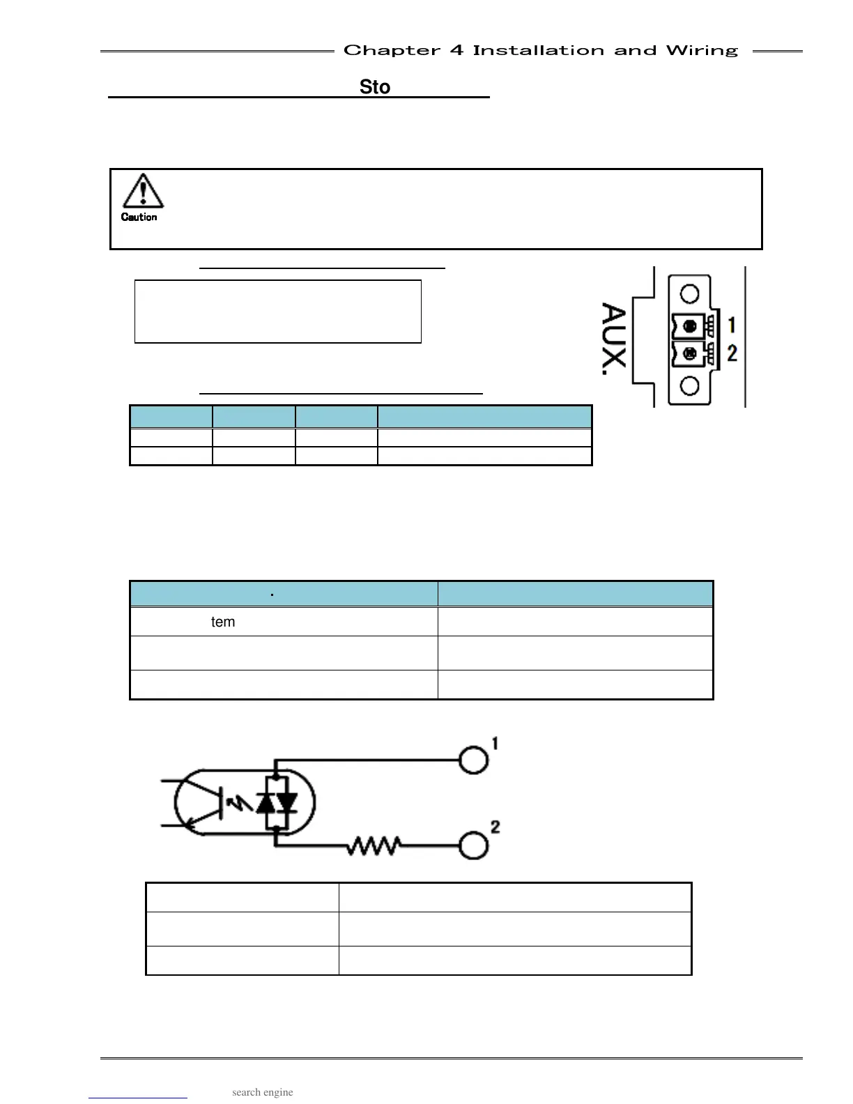
4-10-1 STOP Signal Specifications
Pin no Signal IN/OUT Details
1 STOP+ IN STOP signal input + (DC24V)
2 STOP- IN STOP signal input – (DC 0V)
● Action when external STOP is ON with a Fieldbus Connection
At the point at which the external STOP signal is set to “OFF,” the fastening operation is stopped
and “STOP” is displayed in the upper section of the MFC display unit. Also, the PLC I/O output signal
“READY” turns “OFF.”
● Action of External Emergency Stop Signal according to System/Communication mode
System Structure
・
・・
・
Communication Axis
Function
Single System Acts on the Unit itself.
Multi System : MASTER Axis
Acts on the Units of all connected
spindles.
Multi System: SLAVE Axis Acts on the Unit itself.
● Output Circuit
Bidirectional Photo coupler
PC354N1T (SHARP) or equivalent product
Input Voltage
11.4 to 26V * Recommended: 12V (5mA)/24V
(10mA)
Input Resistance 2.2K
Manufacturer: Phoenix Contact
Type: Cable connector
Model: MC 1,5/2-STF-3,81
Caution
CautionCaution
Caution