Chapter 8 System Operation
PAGE 8- 2
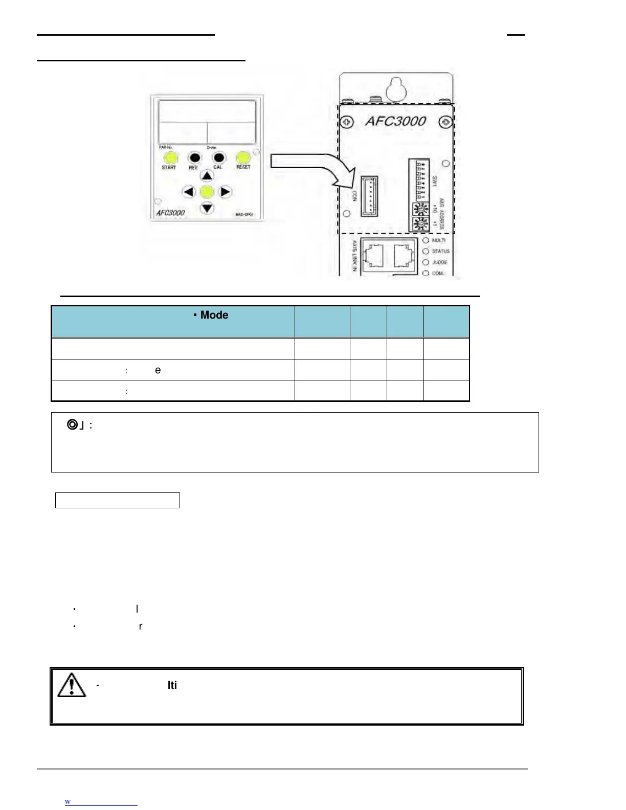
8-1 Controller Display Device
• Correspondence table for Display control switch function (based on mode setting)
System Configuration
・
・・
・
Mode Setting
(DIP SW1 No. 8 & Data No. SYS-003)
START REV. CAL RESET
Single System
○ ○ ○ ○
Multi System
:
Master (MASTER Spindle)
◎ ◎ ◎ ◎
Multi System
:
Slave (SLAVE Spindle)
× × ○ ○
「
「「
「◎
◎◎
◎」:
」:」:
」:Functions on the tools connected to the MASTER (including the Master)
「
「「
「○
○○
○」:
」:」:
」:Functions only on the tool connected to the (single) controller
「
「「
「×
××
×」:
」:」:
」:Does not function
START Pushbutton
For a Single System this push-button initiates the fastening cycle. If the controller is under NORMAL start
mode, a pulse of 200~500 ms activates the cycle. If the start mode is DEADMAN, the signal has to be
active until the fastening ends, otherwise the cycle will be stopped and results stored from the point the
cycle was stopped. If the the 1
st
Torque (or Angle) is not reached, the fastening results and torque curve
will not be stored. (See section 4-12-2 for switch SW1 settings concerning start mode operation)
For a Multi System, the function of the Master (Master Spindle) and Slave (Slave Spindle) are different.
・
Master …All of the connected spindles including Master start fastening.
・
Slave … Start pushbutton does not function
・
・・
・
With the multi system,
spindles may be bypassed (not selected to run) in the
sequence program. Spindles not set to run in a selected
or cycle
Caution