Chapter 8 System Operation
PAGE 8- 8
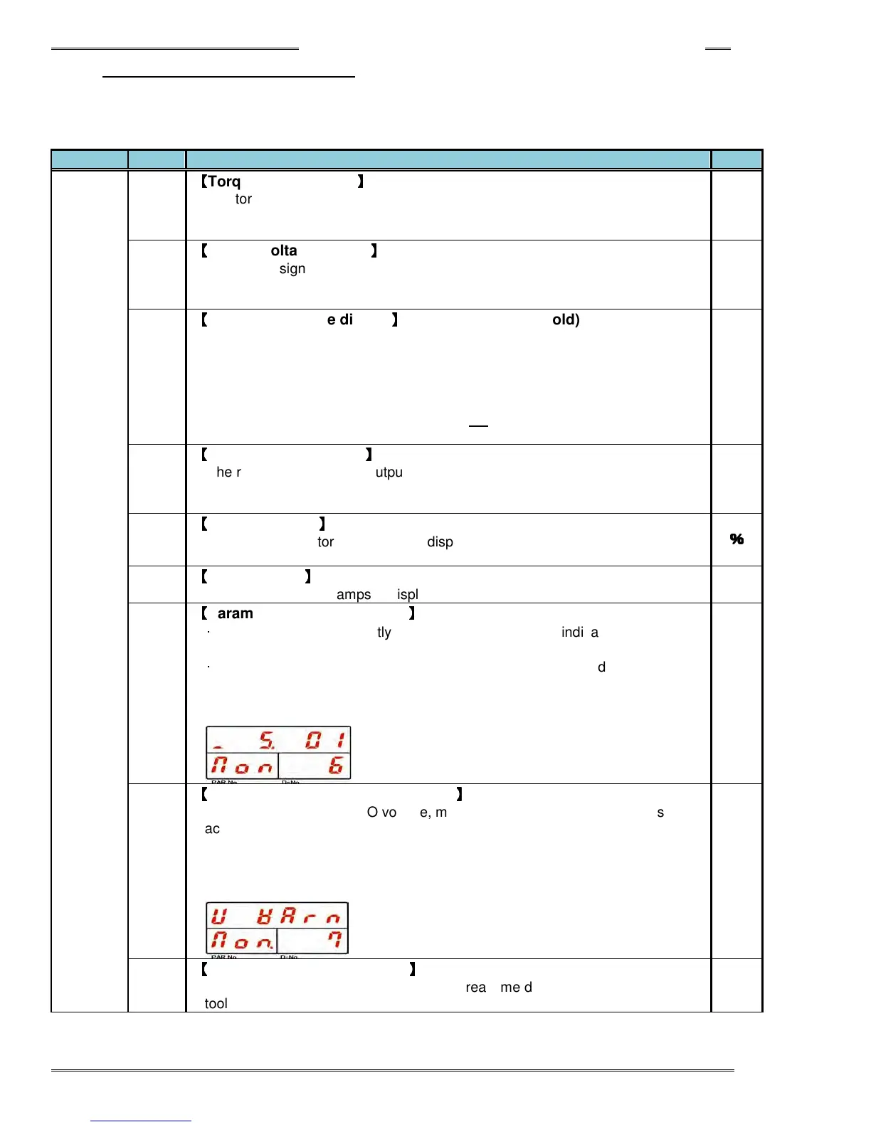
8-3-2 Real Time Display Mode
The following data is displayed in Real Time Display Mode. (“Non” (Monitor) is indicated in the PAR No.
display. By pressing the [▲] or [▼] push-button, the “D-NO” can be changed ±1. The numbers can be
advanced 5 at a time by holding the [▲] or [▼] push-button longer.
Non.
000
【
【【
【
Torque value display
】
】】
】
The torque value from the torque transducer is displayed in real time.
The torque voltage that is converted to the full scale torque is output by
pressing [CAL] pushbutton.
Nm
001
【
【【
【
Torque voltage display
】
】】
】
The torque signal voltage from the torque transducer is displayed in real time.
The torque voltage with about Δ3.7V potential difference is output by pressing
[CAL] switch.
mV
002
【
【【
【
Peak torque value display
】
】】
】
(Peak torque value hold)
The peak torque, measured since the last time the [RESET] switch was
pressed, is displayed in real time.
When the [SET] pushbutton is pressed during this display, the motor is locked
for up to one minute allowing the spindle to be checked with a torque wrench
while displaying the reaction torque. Press RESET to unlock the Motor before
one minute has expired. WARNING: Do not repeat this procedure repetitively
or the motor will overheat.
Nm
003
【
【【
【
Angle rotation display
】
】】
】
The rotation angle of the output shaft since the last time the display mode was
switched to Real Time Display Mode is displayed. Turning the tool output
square will also read in this mode.
deg
004
【
【【
【
Overload factor
】
】】
】
The current monitor load factor is displayed. If the load factor goes over 100,
an overload “A08-10” abnormal occurs
%
%%
%
005
【
【【
【
Current value
】
】】
】
The current value in amps is displayed.
A
006
【
【【
【
Parameter / Sequence Value
】
】】
】
・
Single system: The currently selected parameter No. is indicated (P. 01 to P.
32).
・
Multi system: The currently selected sequence No. is indicated (S. 01 to S.
32).
Also, if pin No. 3 of SW2 on the Controller bottom panel is ON, [ _ ] is indicated
at the far left of the upper display (indicating the PLC IO
STOP is disabled
).
007
【
【【
【
ZERO / CAL Voltage Error Warning
】
】】
】
If the CAL voltage or ZERO voltage, measured when the control power is
activated, when the self-checking is performed at the start of fastening, when
the CAL switch of the indicator is pressed, or when the RESET signal is turned
“ON,” is of an error warning value, the indication (V Warn) shown in the
drawing below will be indicated. When the RESET signal is turned “ON” after
the warning indication, the [------] is re-indicated.
008
【
【【
【
Tool Rotation Speed display
】
】】
】
The current rotation speed is indicated in real time during the operation of the
tool.