Chapter 4 Installation and Wiring
PAGE 4-32
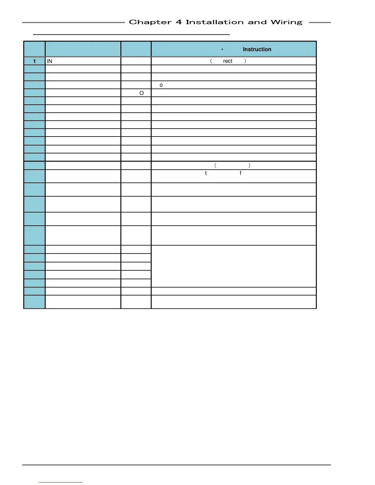
4-6-4 PLC IO Signal (Multi System:
::
:Unit set as SLAVE)
IN: Input Signal
OUT: Output Signal NC: Normal Close NO: Normal Open
Pin
No.
Signal Name IN/OUT Function
・
・・
・
Usage Instruction
1 IN COMMON IN
Input signal common
(
Bi-directional
)
2 IN NC
Not used
3 IN NO
Not used
4 IN NO
Not used
5 IN NO
Not used
6 BYPASS IN NO
Unit turns to BYPASS mode while inputting "ON"
7 IN NO
Not used
8
IN NO
Not used
9
IN NO
Not used
10
IN NO
Not used
11
IN NO
Not used
12
IN NO
Not used
13 IN NO
Not used
14 OUT COMMON OUT
Output signal common
(
Bi-directional
)
15 REJECT(NG) (Slave) OUT NO
Output when the fastening result of the Slave spindle is a
REJECT.
16 ACCEPT(OK) ( Slave ) OUT NO
Output when the fastening result of the Slave spindle is an
ACCEPT.
17 ABNORMAL ( Slave ) OUT NO
Output when an Abnormal condition on the Slave spindle
18 READY ( Slave ) OUT NO
Indicates the Slave spindle is ready to operate and inputs are
enabled.
19 BUSY ( Slave ) OUT NO
Output after a START signal is received from the Slave spindle
and active until the fastening cycle is complete and the READY
signal is output.
20
PAR SELECT BIT 0 ( Slave )
OUT NO
Output confirmation of the Slave spindle PARAMETER SELECT
0~4 selections.
21
PAR SELECT BIT 1 ( Slave )
OUT NO
22
PAR SELECT BIT 2 ( Slave )
OUT NO
23
PAR SELECT BIT 3 ( Slave )
OUT NO
24 PAR SELECT BIT 4 ( Slave )
OUT NO
25 - OUT NO Not used
26 BYPASS ( Slave ) OUT NO
Output when the Slave spindle is bypassed either from bypass
input signals or from the controller’s bypass switch.