Chapter 4 Installation and Wiring
PAGE 4-9
4-2
Tool Dimensions
Tool dimensions and mounting specifications are critical in determining the design of the mounting plate of
the tool assemblies. Tools are offered with two connector (exit) options.
(Note: All tool drawings may be downloaded from FEC website “Support” section)
Provide adequate clearance to ensure that the tool assemblies do not come in contact
with any object. (Anything touching tool may prevent transducer from working correctly)
Failure to provide adequate clearance may result in torque inaccuracies in the
monitoring capability of the system or possible damage to the tool assembly
Refer to PAGE 4-21 for tool installation.
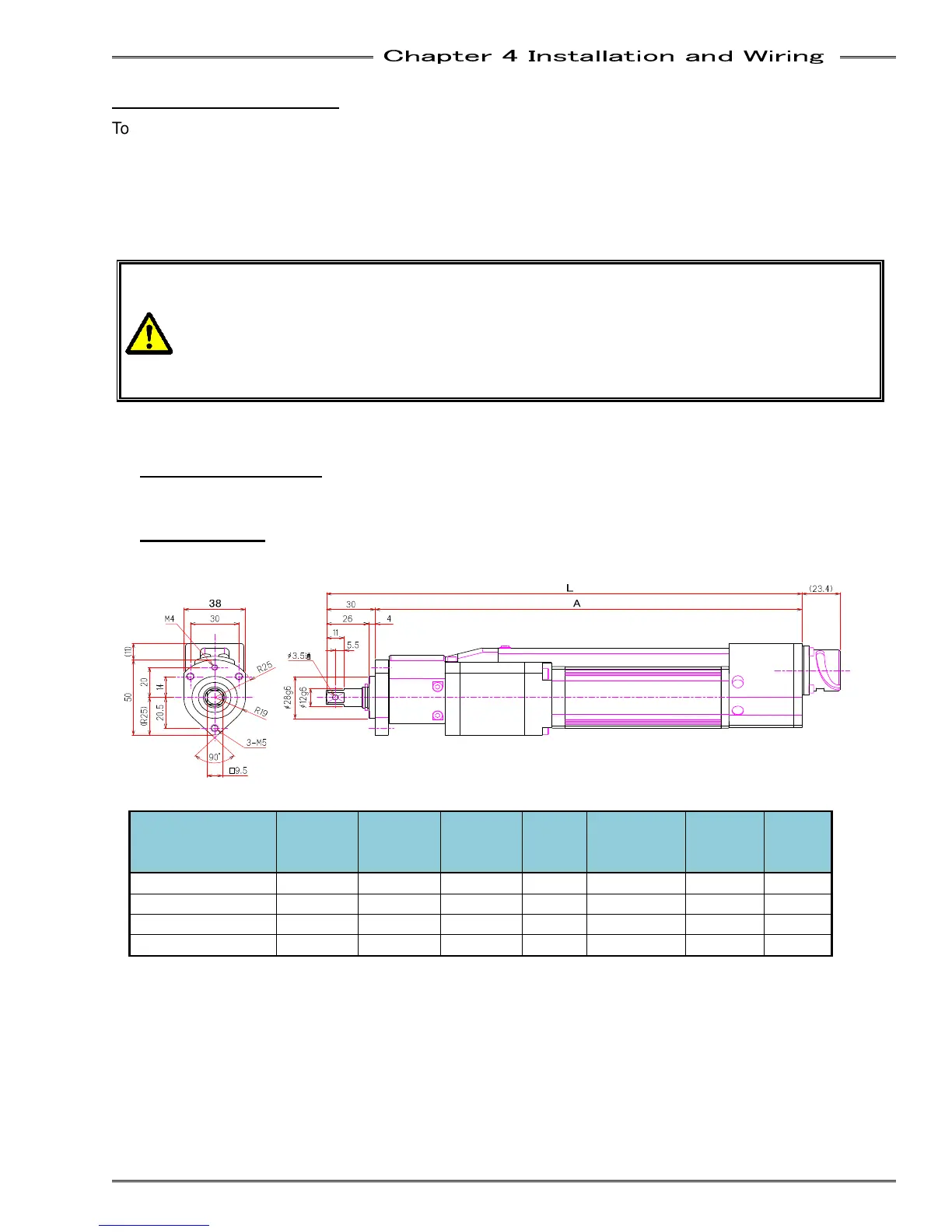
4-2-1 Straight Type
Standard Tool
● CFT-101RS1-S, CFT-201RS1-S, CFT-281RS1-S , CFT-401RS1-S
Tool Type
Max.
Torque
[Nm]
Max.
RPM
[rpm]
Min.
RPM
[rpm]
Mass
[kgf]
Square
Drive
[□mm]
Length
L
[mm]
A
[mm]
CFT-101RS1-S 10 3,000 1 1.3 9.5 275 245
CFT-201RS1-S 20 1,293 1 1.4 9.5 290 260
CFT-281RS1-S 28 992 1 1.4 9.5 293 263
CFT-401RS1-S 40 712 1 1.4 9.5 293 263