Chapter 4 Installation and Wiring
PAGE 4-39
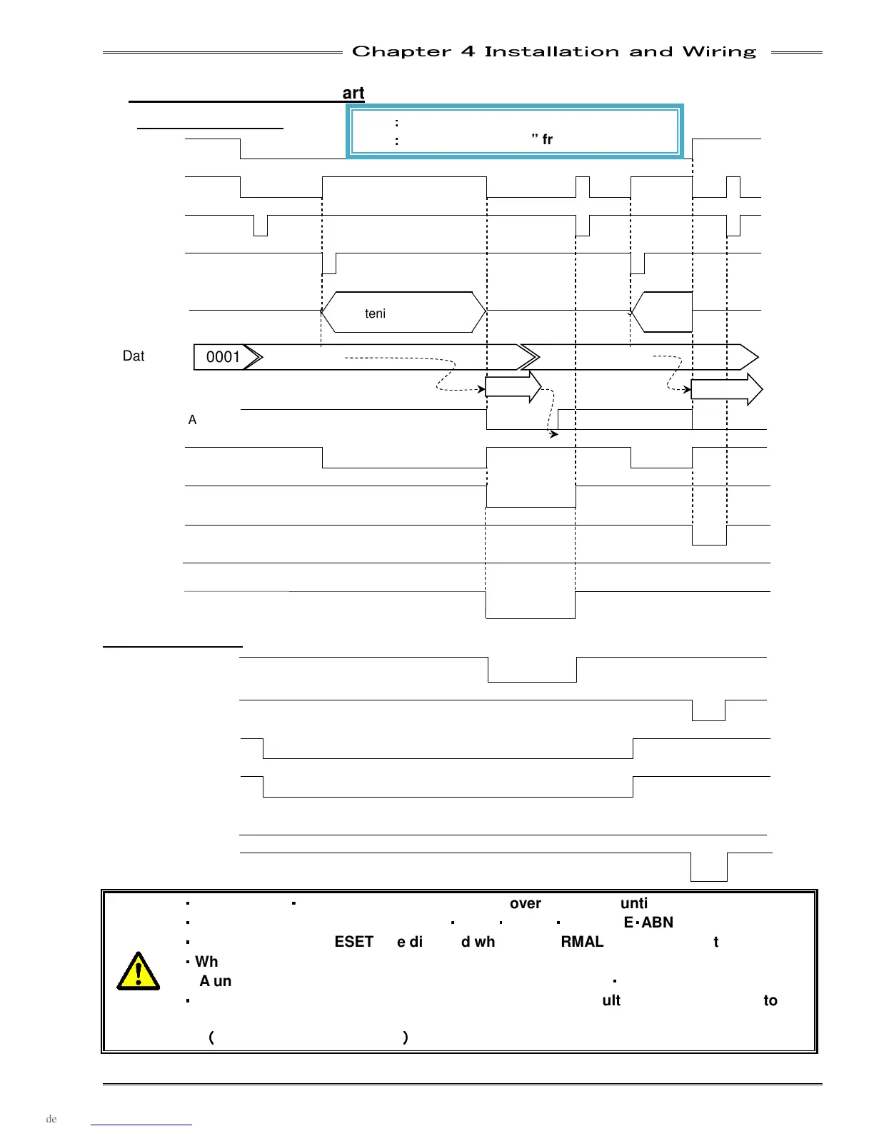
4-6-7 Fastening Timing Chart
Basic Control Signal
STOP OFF ON
READY OFF ON
RESET OFF ON
START OFF ON
Fastening
Operation
Fastening Data Available
OFF ON OFF ON
BUSY
OFF ON OFF
ACCEPT OFF ON
REJECT OFF ON
ABNORMAL OFF
END OFF ON
Signal of each unit
1
st
Spindle ACCEPT(OK
)
OFF ON
1
st
Spindle REJECT(NG)
OFF
ON
2
nd
Spindle BYPASS(IN)
ON OFF
2
nd
Spindle BYPASS(OUT)
ON OFF
2
nd
Spindle ACCEPT(OK)
OFF
2
nd
Spindle REJECT(NG)
OFF ON
・
・・
・
Input RESET
・
・・
・
START signal with a pulse of over 100ms (or until BUSY is confirmed)
・
・・
・
Interlock START signal with READY
・
・・
・
STOP
・
・・
・
RESET
・
・・
・
REVERSE
・
・・
・
ABNORMAL signal
・
・・
・
All inputs (except RESET) are disabled when ABNORMAL signal is output
・
・・
・
When you output a BYPASS signal to a unit, BYPASS is output immediately
A unit in BYPASS mode does not output I/O ACCEPT(OK)
・
・・
・
REJECT(NG) signals
・
・・
・
ID data is input from the RS232C interface. AXIS LINK result outputs in addition to
ID data at the start time of fastening will output after fastening is completed.
(
((
(
Holds data until next input
)
))
)
OFF
:
::
:
Contact is “Open” from PLC side
ON
:
::
:
Contact is “Closed” from PLC side
0003
0002
0001
Fastening Operation
Fastening
Operation
ID Data Output
0002
0003