Chapter 5
I/O
Expansion Unit
Page 5-13
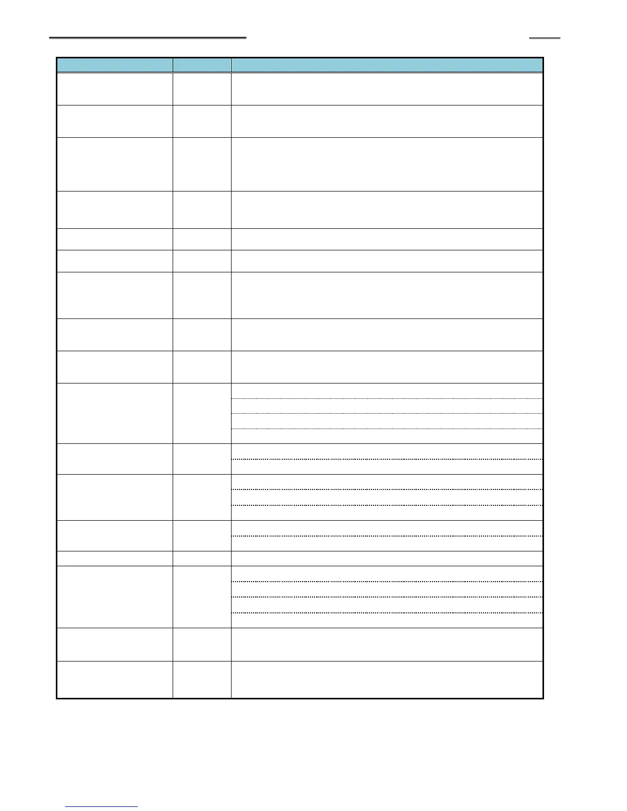
●Individual Spindle Output Signals (spindle 1 to 32)
Description of Function/Usage
Output when the fastening result is a REJECT. Indicates that the spindle
has failed achieving the fastening limits. This output remains active until
the START signal or RESET signal is input.
Output when the fastening result is an ACCEPT. Indicates that the spindle
is within fastening limits. This output remains active until the START
signal or RESET signal is input.
Output when an Abnormal condition occurs. This signal indicates that the
spindle has detected an internal fault and can no longer proceed. The
fault maybe generated during a self-check function (see AFC1500
Operation Manual for troubleshooting). The RESET signal clears the
abnormal condition.
Output when the spindle is in the READY condition. Indicates spindle is
ready to operate and inputs are enabled. This signal is inactive (off) when
the BUSY output is active (on).
Output after a START signal is received, and remains active until the
fastening cycle is complete and the READY signal is output.
Signal is active when the spindle is bypassed either from San Unit bypass
input signal or from the San Unit bypass switch.
Output while operating in D-No. 315 “Torque Recovery Time” when the
fastening parameter D-No. 006 “After Fastening Operation” Torque
Recovery is enabled.
Output confirmation of PARAMETER SELECT 1~4 input selections.
Parameter Select bits are active according to what sequence is set from
the sequence select inputs.
Parameter Select 1-4
(Individual)
Output confirmation of INDIV PARAMETER SELECT 1-32 input
selections. Parameter Select bits are active according to what
parameter is set from the parameter select inputs.
Peak torque low limit /peak torque high limit
Final torque low limit/final torque high limit
Start torque inhibit high limit
Final angle low limit/final angle high limit
Differential - angle /Differential + angle
Rate 1 low limit/Rate 1 high limit
Rate 2 low limit /Rate 2 high limit
Rate 3 low limit /Rate 3 high limit
1st time low limit /1st time high limit
2nd time low limit /2nd time high limit
Rundown revolution low limit /rundown revolution high limit
Low current value limit warning/high current value limit warning
Current value error warning
CAL voltage error warning
ZERO voltage error warning
Combination Judgment
Bits 1-8
Used to create “special” outputs formed by using a combination of MFC
Unit outputs in “AND / OR” logic.
Output if one or more fastening steps was not processed during a
fastening operation. Used to confirm if the fastening sequence
processed correctly without skipping a programmed sequence step.