Chapter 2 Specifications
PAGE 2-4
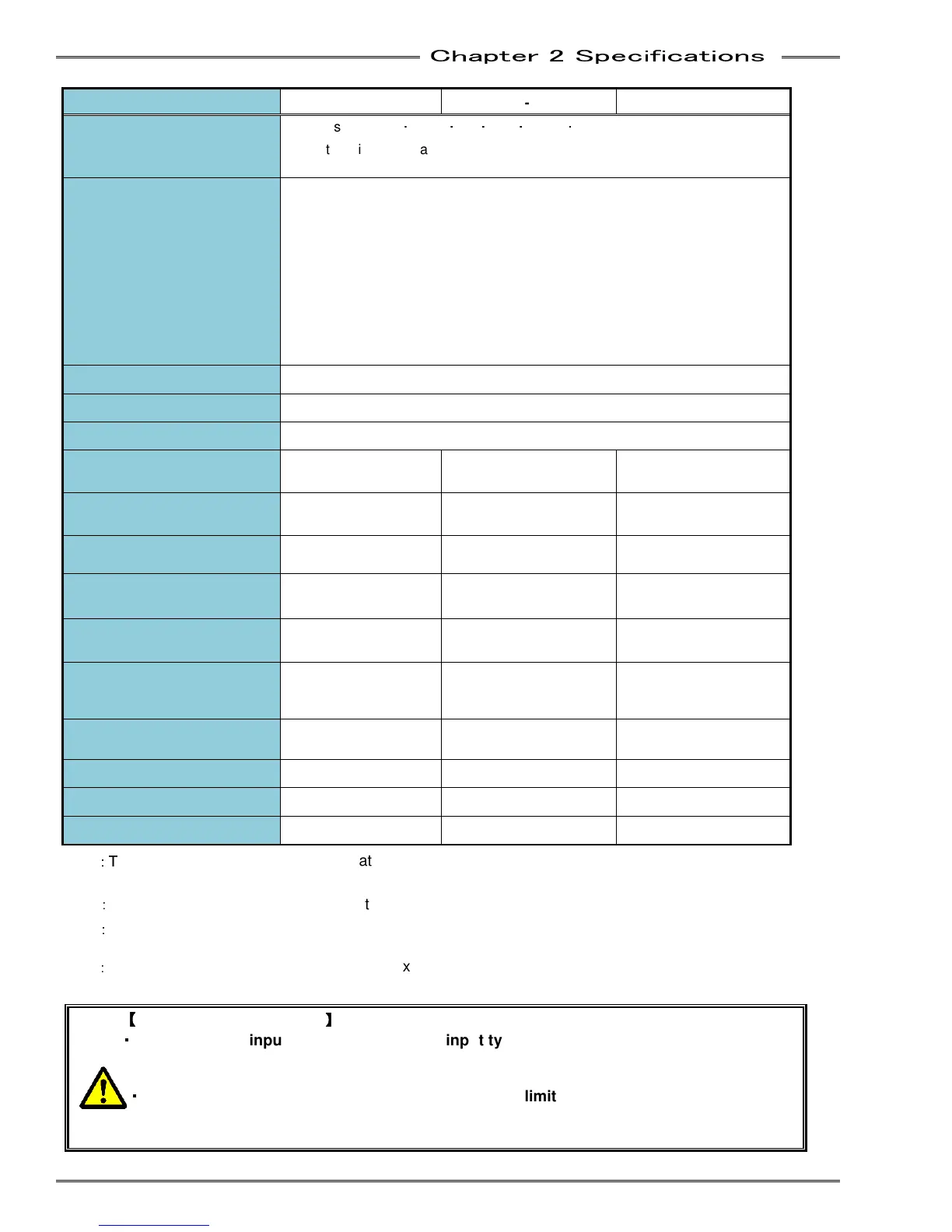
Controller Model MFC-S024 MFC-S060
MFC-S120
RTC (Real Time Clock)
Time display: Year
・
Month
・
Day
・
Hour
・
Minute
・
Second
Retention time: 30 days (in fully-charged state under ambient temperature of
20°C)
Protective Functions
Overload: Load factor of no more than 100%
Driver overheat: Heat sink temperature of no more than 80°C
Overcurrent (short-circuit protection): Excessive current due to output short
circuit or ground fault
Control power voltage drop: Control power voltage outside of 24V DC ± 2.4V
Incomplete soft charging: Incomplete charging of the drive power source
capacitor (used to reduce Inrush current)
Resolver error: Resolver disconnection, tracking error
CPU: CPU watchdog timer error
Insulated Resistance
No less than 50MΩ/500V DC
Dielectric Withstand Voltage
No more than 1500V AC/10mA
SCCR Rating
5KA rms
Inrush Current at Drive at
Power On (AC)
22A max
(duration: <0.5s)
22A max
(duration: <0.5s)
40A
(duration: <0.5s)
Inrush Current at Control
Power On (DC)
15A max
(duration: 36ms)
15A max
(duration: 36ms)
15A max
(duration: 36ms)
Continuous Drive Current (*1)
2.0 Arms 4.0 Arms 5.2 Arms
Momentary Maximum Output
Current
17.0 Arms 42.4 Arms 84.8Arms
Avg. Power Consumption (*4)
(Heat Output)
32Watt (15Watt Idle) 41Watt (15Watt Idle) 137Watt (15Watt Idle)
Allowable Number of Times of
Drive Power ON/OFF (*2)
10 million times 3 million times 2.5 million times
Allowable Drive Power
ON/OFF Cycle (*3)
10 seconds 10 seconds 15 seconds
Heat Radiation Fan
None None 2 (Internal)
Rear Panel Heat Sink
None Provided Provided
Weight (kg)
1.60 1.96 4.92
(*1)
:
T
he allowable current value running at a continuous constant output current (constant load torque). It is a
limited value mainly due to temperature increase of heat sink.
(*2)
:
The life expectancy at max. rated voltage (soft charge resistor (Inrush reducing circuit) no longer works)
(*3)
:
Limited value in the case that cycling power is continued over a long period of time. (No limit for small
“incidental” power cycling)
(*4)
:
Avg. Power Consumption listed is (approx.) and may vary depending on operating conditions (Torque,
Speed, Time, etc.)
【
【【
【
Caution - Power-On cycle
】
】】
】
・
・・
・
The unit power input circuit is a capacitor input type circuit.
A resistor circuit which suppresses inrush current when power is turned on is used
(internal voltage reaches a preset standard and then charges through resistance)
・
・・
・
The resistance of inrush current suppression has a limited cycle life.
Review the power-on cycle referring to the “allowable number of times
be cycled (ON / OFF) listed above.