Chapter 3 System Description
PAGE 3-8
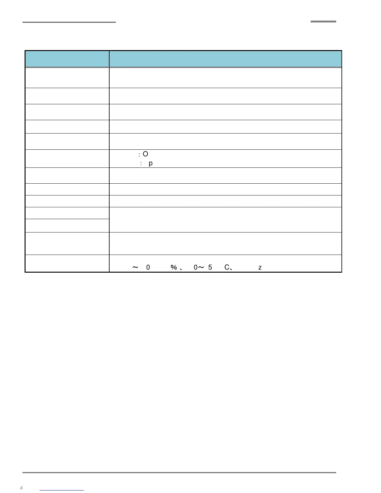
● Controller Front Panel Switches and Connectors
Item
Description
Display Unit
Parameters can be set and fastening results can be checked (with the display
mounted on the controller).
Display unit Installation
Connector
Plug in a connector located on back of display
Special Function
SW1Switch
Allows setting of special fastening functions (See 4-12 for setup)
AXIS No. Switch Allows setting of spindle number (See 4-12 for setup)
AXIS Link Connector
IN/OUT
Communication ports for AXIS LINK (between spindles)
RUN/BYPASS Switch
RUN
:
Operation Mode
BYPASS
:
Spinlde BYPASS Mode
PC communication
Communication port for AFC3000 user console software
Control Power Connector
Control power connector (DC 24V)
RS232C Connector Fastening data output port
Sensor Connector
Motor cable connectors
Motor Power Connector
Standard I/O Connector
Input:12 / Output:12
External (PLC) I/O signal connector
AC Power Input
Connector
AC Motor Power connector
AC200
~
230V (±10
%
)
、
180
~
252VAC
、
50/60Hz