Chapter 4 Installation and Wiring
PAGE 4-2
Review Chapters 1 and 2 prior to designing a System. If the requirements and specifications in these two
(2) Chapters are not addressed, there is a chance of degraded System performance.
WARNING: Follow Lockout/Tagout and other safety precautions when connecting and/or
disconnecting cabling, wiring, and equipment.
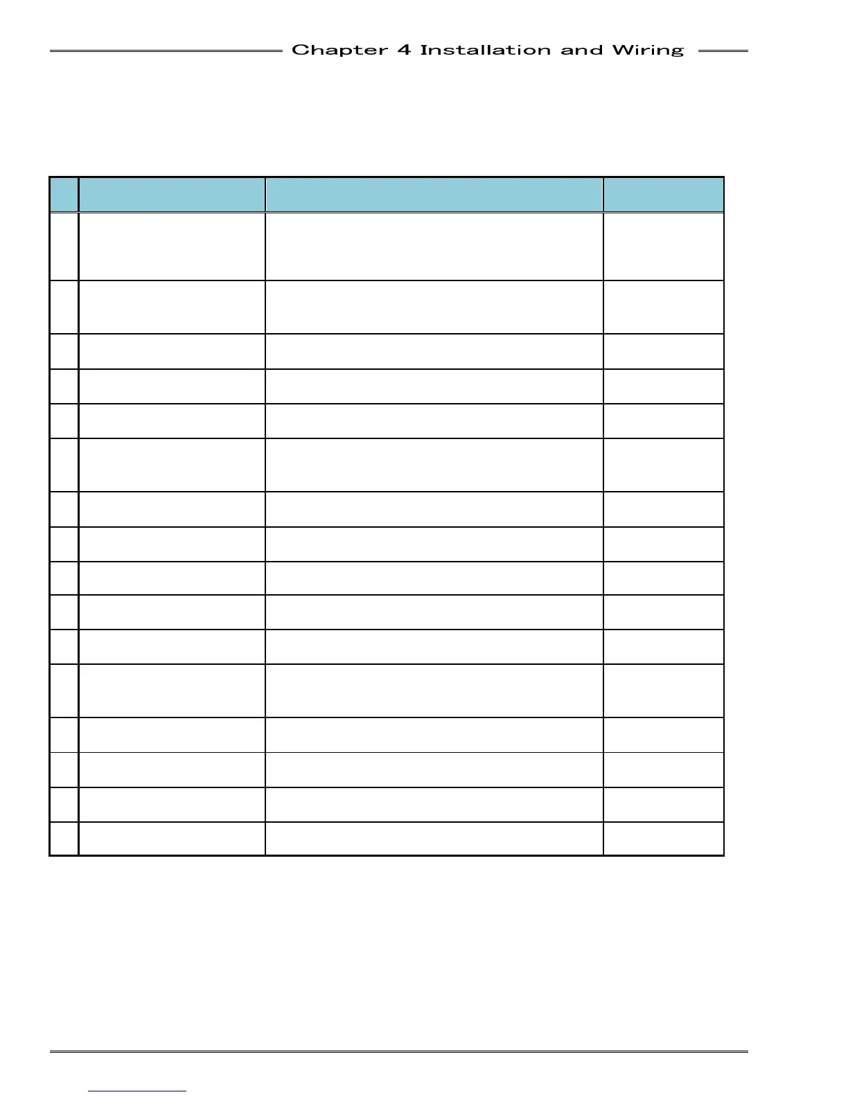
№
Item Contents Reference Page
1
Select correct tool size
Keep torque range between 50% and 75 % of
tool capability for best performance.
Ensure fastening bolt pattern and tool mounting
patterns are compatible.
PAGE 4-9
2
Design tool mounting plate,
pow
assemblies.
Design of mounting plate / powerhead requires
adherence to several specifications.
PAGE 4-16
3
Select correct controller
the tool selected.
Different tool motors require different Servo
Amplifiers. Ensure the correct one is selected.
PAGE 4-9~12
4
protectors.
Circuit protection for controller
separate from other units.
PAGE 4-20
5
Select an air handling unit
(as required).
Select an air handling unit applicable to the
environmental conditions (A/C, Heat Exch., etc.)
PAGE 4-3~6
6
Select an adequate PLC.
Select a PLC which will facilitate direct
connection to the AFC3000 System I/O (24 VDC).
PAGE 4-29
7
logic.
A PLC logic program can be written using signal
descriptions and timing charts provided.
PAGE 4-30~37
8
Select NEMA 12 enclosure.
Keep clearances among units according to the
recommended installation layout.
PAGE 4-7,8
9
Set MFC Unit dip switches.
Check the setting before connecting the Unit PAGE 48~50
10
Mount the controller
enclosure.
Refer to recommended installation layout. PAGE 4-8
11
Wire power connections.
Connect the power cables.
AND POLARITY PRIOR TO APPLYING POWER
PAGE 4-18,19
12
Wire I/O connections.
Connect all I/O wiring. VE
SOURCE AND POLARITY PRIOR TO
CONNECTION.
PAGE 4-25~28
13
Connect homerun cables.
, then connect cables for
every motor/resolver and preamplifier.
PAGE 4-22
14
Turn on the equipment.
VERIFY WIRING AND THE VOLTAGE OF ALL
POWER SUPPLIES PRIOR TO POWERING UP.
15
Input preset data.
Set the preset data for torque, angle, speed, time,
etc.
16
Verify normal function. Confirm normal operation.