Chapter 4 Installation and Wiring
PAGE 4-23
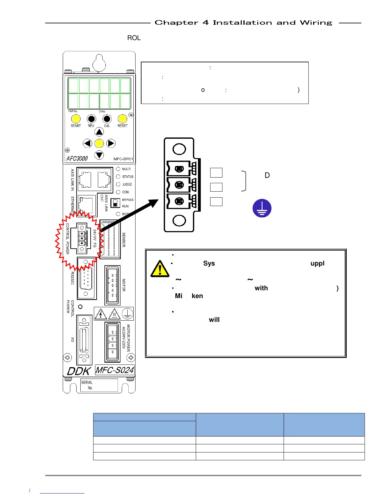
Supply 24VDC to the CONTROL POWER connector located on the left middle area of the unit.
・
・・
・
Always ground the equipment!
・
・・
・
For Multi System: The timing of the power supply for
spindle No.1 needs to be same as for spindle No. 2
~
~~
~
32 or later than No. 2
~
~~
~
32
・
・・
・
Be careful to connect with correct polarity (+/-)
Mistaken polarity may cause electrical shock or
damage to the controller
・
・・
・
If 24VDC power drops below 18VDC (approx.), the
controller will reboot automatically. 24VDC power
source should be separate DC supplies if
controllers are to be powered from separate
power-on circuits
Wire Color
(Recommended 20 AWG)
Signal
MFC-S120
1 RED 24VDC
2 WHITE 0V
3 BLACK Field Ground
Cable side connector
:
Phoenix Contact (MFC.)
Type
:
MC 1,5/2-STF-3,81
Cable side connector case
:
Phoenix Contact (MFC.)
Type
:
KGG-MC 1.5/3
1 24V
2 0V
3 FG
24VDC +/-
0.3A