Electric – VFD
Hardware Signals
4 – 20 m A analog output – Signal from the
Quantum™ to provide the speed setpoint to the VFD
controller. The VFD’s controller and hardware will
need to be configured to the minimum and maximum
desired speed. The minimum speed will vary
depending on compressor type, consult the factory for
application assistance.
4 – 20 mA analog input – Analog input channel on
the Quantum™ to monitor the actual RPM’s of the
drive. This signal is for monitoring purposes only.
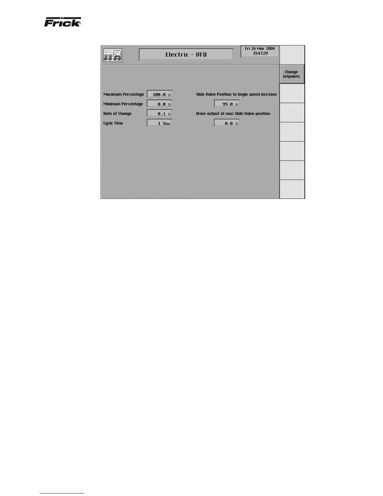
Setpoints related to the VFD speed control output:
Maximum output – Setpoint used to select the
maximum operating speed of the VFD. Selectable
from 1-100% of the Quantum™’s 4-20 mA signal.
Minimum output – Setpoint used to select the
minimum operating speed of the VFD. Selectable
from 1-100% of the Quantum™’s 4-20 mA signal.
Rate of change - Setpoint used to adjust the speed
changes sent to the VFD based on the capacity
control Selectable from .1-25% of the 4-20 mA signal.
Cycle Time – Setpoint used in conjunction with the
Rate of change setpoint to adjust the time between
speed changes sent to the VFD. Selectable from 1-30
seconds.
Slide Valve Position to begin Speed Increase –
The Slide Valve position that must be obtained before
the VFD will begin increasing speed. Selectable from
0-100% of the compressors Slide Valve position. This
setpoint is used in conjunction with the Drive Output
at Max SV position.
Drive Output at Max SV position – The desired
speed of the VFD when the compressors Slide Valve
position reaches 100%. This setpoint is selectable
from 1-100% of the Quantum™’s 4-20 mA signal and
is used in conjunction with the Slide Valve Position to
begin Speed Increase.
NOTE: See Electric, VFD, Engine, Turbine flowchart
for further information.
FRICK
QUANTUM™ COMPRESSOR CONTROL PANEL S90-010 O
OPERATION Page 27