S90-010 O FRICK
QUANTUM™ COMPRESSOR CONTROL PANEL
Page 74 OPERATION
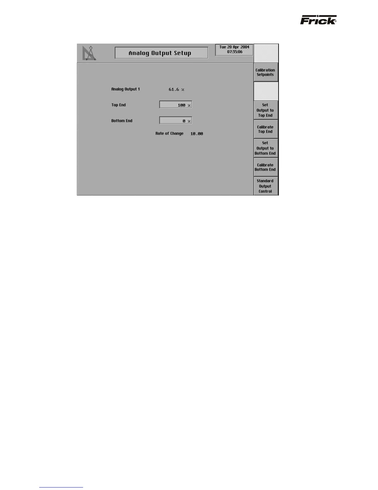
Analog Output Setup
Use this screen only if the analog output signal needs
calibration and it can not be calibrated at the device.
The Quantum’s analog outputs have a range of
approximately 0 to 25 mA, but most devices that are being
controlled by the Quantum require a signal that varies
between 4 and 20 mA. To restrict the analog outputs to
the proper values, each of the outputs must be calibrated
before they can be used. Every output channel has a Top
End and a Bottom End setpoint that are used for
calibration. Both values can be set from 0% to 100%. The
output channel’s maximum value is represented by 100%
and its minimum value is represented by 0%. To calibrate
the channel the Top End percentage is decreased until the
maximum output for the channel is limited to 20mA. Also,
the Bottom End percentage is increased until the minimum
output for the channel is 4mA.
Below is a step by step procedure for calibrating one
analog output.
1. Make sure that the PID control for that output
channel is disabled.
2. Set up a meter to read the channel’s output value
in milliamps.
3. Go to the Analog Output Calibration page for the
output that is being calibrated.
4. Press the [Set Output to Top End] key and the
output value should jump to 100%.
5. Press the [Calibrate Top End] key.
6. Check that the Rate of Change value is 10.00. If
it is not, press the [Select Rate of Change] key
until it is displayed as 10.00.
7. If the channel’s output is greater than 20 mA
press the [Decrease Top End] button. If the
channel’s output is less than 20 mA, press the
[Increase Top End] key. Use these keys to find
the output value closest to 20 mA.
8. Press the [Select Rate of Change] key once to
decrease the Rate of Change to 1.00.
9. Use the [Increase Top End] key and the
[Decrease Top End] key to again find the value
closest to 20 mA.
10. Repeat steps 8 and 9 for Rate of Change values
of 0.1 and 0.01 to bring the output value as close
as possible to 20mA.
11. Press the [Previous Screen] key.
12. Press the [Set Output to Bottom End] key and
the output value should drop to 0%.
13. Press the [Calibrate Bottom End] key.
14. Check that the Rate of Change value is 10.00. If
it is not, press the [Select Rate of Change] key
until it is displayed as 10.00.
15. If the channel’s output is greater than 4 mA,
press the [Decrease Bottom End] key. If the
channel’s output is less than 4 mA, press the
[Increase Bottom End] key. Use these keys to
find the output value closest to 4 mA.
16. Press the [Select Rate of Change] key once to
decrease the Rate of Change to 1.00.
17. Use the [Increase Bottom End] key and the
[Decrease Bottom End] key to again find the
value closest to 4 mA.
18. Repeat steps 16 and 17 for Rate of Change
values of 0.1 and 0.01 to bring the output value
as close as possible to 4mA.
19. Press the [Previous Screen] key.
20. Press the [Standard Output Control] key to
allow the output to return to standard control.
21. If the output channel is being used for PID
control, re-enable the PID.