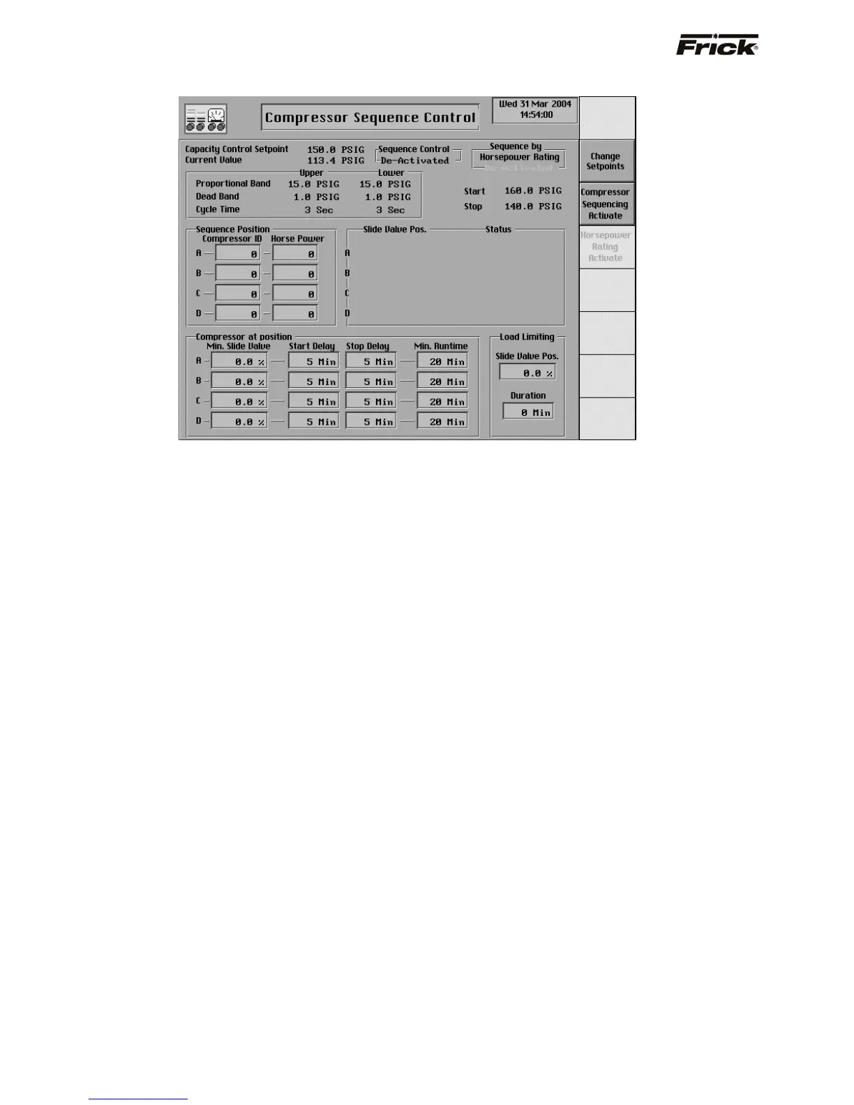
Compressor Sequence Control (MODE 1)
This screen is shown if the Sequence Mode 1
Compressor Sequencing option was selected in Panel
Setup. For quick access to this screen there is a
[Compressor Sequence Setpoints] screen key on the
Operating Status -2 screen. This sequencing is intended
for compressors that are operating to maintain the same
Capacity Control setpoint. The settings on this screen are
used to sequence the compressors when a compressor is
in the remote start mode of operation and in remote Slide
Valve mode and available to run i.e. not in shutdown
(cutout) or Recycle Delay. This sequence control is only
used for compressors with a variable Slide Valve and will
work with existing Frick RWB, RXB, and RXF panels.
Serial communication using the Com-1 port is used for this
sequencing (drawing nos. 640A0042 and 640A0050.
The setpoints that are currently being used for Capacity
Control are only shown here for referencing. These
setpoints are taken from the active Capacity Control
settings at the panel where Compressor Sequencing is
activated. Current Value is the current reading or actual
reading of the pressure or temperature process variable
that was chosen as the Capacity Control method.
Compressor Sequencing can be enabled from panel setup
and entered on more than one panel. However; for proper
control, only the Compressor Sequencing settings at one
panel should be made active. The following describes how
Compressor Sequencing uses the Capacity Control
setpoints:
Capacity Control - This is the reading that the control
sequence will attempt to maintain for the indicated
process. This setpoint is used to control the loading
and unloading of the compressors.
The Proportional Band setpoint determines a range of
Capacity Control values where proportionally timed
pulsed output is used. Beyond the proportional band
the output is continuously energized. The length of
time the output will be pulsed on is proportional to the
distance the current reading of the process variable is
from the Capacity Control setpoint. The further the
distance from setpoint, the longer the output is pulsed
on and the shorter the output is off. The closer the
distance to setpoint, the shorter the output is pulsed
on and the longer the output is off. If the actual
reading is midway from setpoint, the output is on and
off an equal amount of time. (See Cycle Time).
Upper Proportional Band - A band, measured
in the units of the Capacity Control setpoint,
above the upper dead band, where proportional
load control is used. If the actual reading rises
into this proportional band, the load output will be
pulsed as explained above in the description
about proportional band.
Lower Proportional - A band, measured in the
units of the Capacity Control setpoint, below the
lower dead band, where proportional unload
control is used. If the actual reading falls into this
proportional band, the unload output will be
pulsed as explained above in the description
about proportional band.
Upper Dead Band - A band, measured in the
units of the Capacity Control setpoint, above the
setpoint at which the compressor will neither load
nor unload.
Lower Dead Band - A band, measured in the
units of the Capacity Control setpoint, below the
setpoint at which the compressor will neither load
nor unload.
S90-010 O FRICK QUANTUM™ COMPRESSOR CONTROL PANEL
Page 50 OPERATION