Low RPM Alarm - If the RPM is less than or equal to
this setpoint, for the alarm time delay, an alarm
occurs.
Low RPM Shutdown - If the RPM is less than or
equal to this setpoint, for the shutdown time delay, the
compressor will shut down.
Low RPM Alarm Delay - The minimum time in
seconds that the RPM is less than or equal to the Low
RPM alarm setpoint before notification of the alarm.
Low RPM Shutdown Delay - The minimum time in
seconds that the RPM is less than or equal to the Low
RPM shutdown setpoint before the compressor will
shut down.
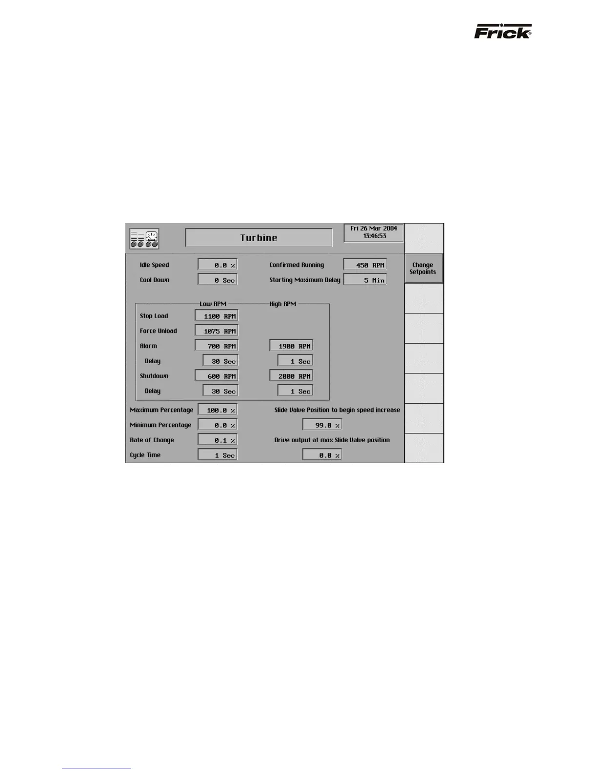
Confirmed Running (RPM) - The value that the RPM
is greater than or equal to consider the compressor
running.
Starting Maximum Delay - The time delay required
for the Slide Valve to unload below the Highest Slide
Valve position to allow starting the compressor
setpoint and the engine RPM’s to reach the confirmed
running RPM’s setpoint.
NOTE: See Electric, VFD, Engine, Turbine flowchart
for further information.
Turbine
Hardware Signals
4 – 20 mA analog output – Signal from the
Quantum™ to provide the speed setpoint to the
speed governing device. The speed governing
device’s controller (i.e. Electronic Governor) and
hardware will need to be configured to the minimum
and maximum desired speed. The minimum speed
will vary depending on compressor type, consult the
factory application assistance.
4 – 20 mA analog input – Analog input channel on
the Quantum™ to monitor the actual RPM’s of the
drive. This signal can be sent to the Quantum™ from
the speed-governing device if available or generated
from a magnetic pickup located on the flywheel teeth
wired to a frequency to 4-20 mA converter.
Setpoints related to the Turbine speed control output:
Maximum output – Setpoint used to select the
maximum operating speed. Selectable from 1-100%
of the Quantum™’s 4-20 mA signal.
Idle Speed - If the Slide Valve is less than the
Highest Slide Valve Position to allow starting the
compressor setpoint, the Engine will be at idle.
Minimum output – Setpoint used to select the
minimum operating speed. Selectable from 1-100% of
the Quantum™’s 4-20 mA signal.
Rate of change - Setpoint used to adjust the speed
changes sent to the VFD based on the capacity
control requirements. Selectable from .1-25% of the
4-20mA signal.
Cycle Time – Setpoint used in conjunction with the
Rate of change setpoint to adjust the time between
speed changes sent to the VFD. Selectable from 1-30
seconds.
Slide Valve Position to begin Speed Increase –
The Slide Valve position that must be obtained before
the speed will begin to increase. Selectable from 0-
100% of the compressors Slide Valve position. This
setpoint is used in conjunction with the Drive Output
at Max SV position.
Drive Output at Max SV position – The desired
speed of the engine/turbine when the Slide Valve
position reaches 100%. This setpoint is selectable
from 1-100% of the Quantum™'s 4-20 mA signal and
is used in conjunction with the Slide Valve Position to
begin Speed Increase.
S90-010 O FRICK QUANTUM™ COMPRESSOR CONTROL PANEL
Page 30 OPERATION