• Capacity Up (Output 2) - This output is
energized to signal the next panel to load the
compressor.
• Capacity Down (Output 3) - This output is
energized to signal the next panel to unload
the compressor.
• Slide Valve > Minimum (Output 8) - This
output is energized to signal the previous
panel that the Slave’s slide valve reading is
above the Minimum Capacity when Running
setpoint.
Input Status (Digital Board 2):
• Start (Input 5) - This input is energized to
signal this panel to start the compressor.
This input is de-energized to signal this
panel to stop the compressor.
• Capacity Up (Input 6) - This input is
energized to signal this panel to load the
compressor.
• Capacity Down (Input 7) - This input is
energized to signal this panel to unload the
compressor.
• Slide Valve > Minimum (Input 4) - This
input is energized to signal this panel that
the Slide Valve reading of the next
compressor is above that panel’s Minimum
Capacity when Running setpoint.
The active capacity control setpoints are shown here for
referencing. The active Capacity Control setpoints are
taken from the Capacity Control settings at this panel.
Actual is the current reading of the pressure or
temperature that was chosen as the Capacity Control
setpoint. For proper control, only one panel should be
selected as the Master for compressor sequencing. The
Master compressor sequence controller attempts to
maintain the Capacity Control setpoint by loading and
unloading in response to the following capacity control
setpoints. The Slave compressor sequence controller is
signaled from a previous panel to load or unload and then
uses the following Capacity Control setpoints to determine
when to pulse the panel’s local Slide Valve load and Slide
Valve unload outputs. The signal for loading or unloading
from the previous panel overrides the Slave’s Capacity
Control settings that might be determining the opposite
local Capacity Control. For example, the Slave’s local
settings could indicate it should be loading but a signal
from a previous panel could be telling it to unload. In this
situation, the Slave will unload but it will pulse according to
its local settings. The Slave’s local settings are used to
determine pulse loading or unloading and if these settings
don’t coincide with the Master’s settings, then improper
pulsing can result. For good Capacity Control, it is
important that each panel is properly setup. The following
describes the compressor sequencing Capacity Control
setpoints:
Capacity Control - This is the reading which the
Master compressor sequence controller will attempt to
maintain. This setpoint at each panel is used to
control the loading and unloading of the compressor.
The Proportional Band setpoint determines a range of
capacity control values where pulsed output is used.
Beyond the proportional band the output is continuously
energized. The length of time the output will be pulsed on
is proportional to the distance the actual reading is from
the Capacity Control setpoint. The further the distance
from setpoint, the longer the output is pulsed on and the
shorter the output is off. The closer the distance to
setpoint, the shorter the output is pulsed on and the longer
the output is off. If the actual reading is midpoint from
setpoint, the output is on and off an equal amount of time.
Upper Proportional Band - A band, measured in the
units of the Capacity Control setpoint, above the
upper dead band, where proportional load control is
used. If the actual reading rises into this proportional
band, the load output will be pulsed as explained
above in the description about proportional band.
When in this band the Master compressor sequence
controller will begin the process of starting the
compressor.
Lower Proportional Band - A band, measured in the
units of the Capacity Control setpoint, below the lower
dead band, where proportional unload control is used.
If the actual reading falls into this proportional band,
the unload output will be pulsed as explained above in
the description about proportional band.
Upper Dead Band - A band, measured in the units of
the Capacity Control setpoint, above the setpoint at
which the compressor will neither load nor unload.
Lower Dead Band - A band, measured in the units of
the Capacity Control setpoint, below the setpoint at
which the compressor will neither load nor unload.
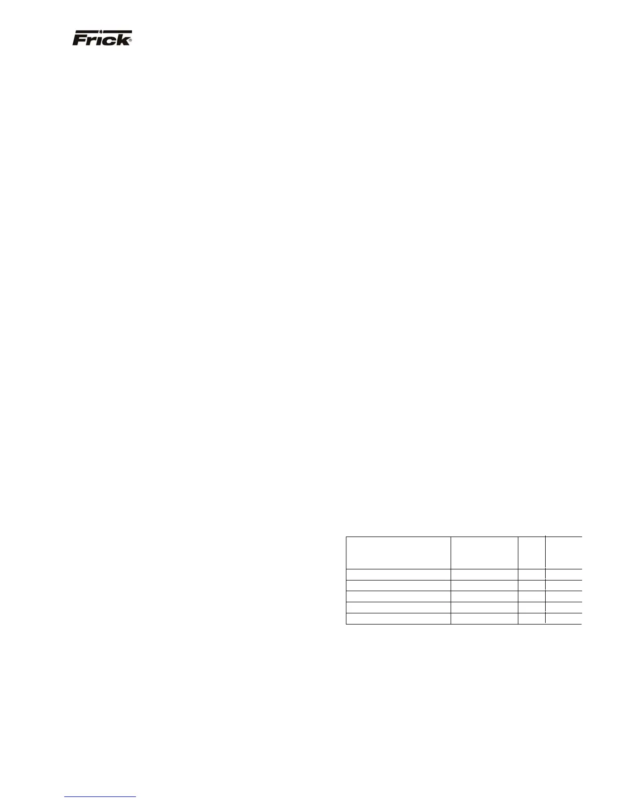
The Cycle Time setpoint determines the amount of time
the output is on and off, when in the proportional band. At
the completion of the cycle time the actual reading and
necessary response is re-evaluated. If a 4 second period
is selected, then the following will result:
Proportional Distance
Actual Reading is
From Setpoint
Output
Pulsed On
(seconds)
Output Off
(seconds)
0 0 4
1/4 1 3
1/2 2 2
3/4 3 1
1 4 0
Upper Cycle Time - This setpoint determines the
amount of time in seconds that the load output is on
and off, when in the upper proportional band. Refer to
the above description about cycle time.
Lower Cycle Time - This setpoint determines the
amount of time in seconds that the unload output is
on and off, when in the lower proportional band. Refer
to the above description about cycle time.
FRICK
QUANTUM™ COMPRESSOR CONTROL PANEL S90-010 O
OPERATION Page 55