5-148
Chap. 5 FUNCTION CODES
F codes
E codes
C codes
P codes
H codes
A codes
b codes
r codes
J codes
d codes
U codes
y codes
Timer (y03 for port 1 and y13 for port 2) Data setting range: 0.0 to 60.0 (s)
y03 or y13 specifies an error processing timer. If the timer count has elapsed due to no response from the other end
when a query has been issued, the inverter interprets it as an error occurrence. See the "No-response error detection time
(y08, y18)" given on the next page.
Baud rate (y04 for port 1 and y14 for port 2)
Data for y04 and y14 Transmission speed (bps)
0 2400
1 4800
2 9600
3 19200
y04 or y14 specifies the transmission speed for RS-485
communication.
For FRENIC Loader (via the RS-485 communications link),
specify the transmission speed that matches the connected
computer.
4 38400
Data length (y05 for port 1 and y15 for port 2)
Data for y05 and y15 Data length
0 8 bits
1 7 bits
y05 or y15 specifies the character length for RS-485
communication.
For FRENIC Loader (via the RS-485 communications link),
no setting is required since Loader automatically sets 8 bits.
(The same applies to the Modbus RTU protocol.)
Parity check (y06 for port 1 and y16 for port 2)
Data for y06 and y16 Parity
0
None
(2 stop bits for Modbus RTU)
1
Even parity
(1 stop bit for Modbus RTU)
2
Odd parity
(1 stop bit for Modbus RTU)
y06 or y16 specifies the property of the parity bit.
For FRENIC Loader, no setting is required since Loader
automatically sets the even parity.
3
None
(1 stop bit for Modbus RTU)
Stop bits (y07 for port 1 and y17 for port 2)
Data for y07 and y17 Stop bit(s)
0 2 bits
1 1 bit
y07 or y17 specifies the number of stop bits.
For FRENIC Loader, no setting is required since Loader
automatically sets 1 bit.
For the Modbus RTU protocol, no setting is required since
the stop bits are automatically determined associated with the
property of parity bits.
No-response error detection time (y08 for port 1 and y18 for port 2)
Data for y08 and y18 Function
0 No detection
1 to 60 1 to 60 s
y08 or y18 specifies the time interval from when the inverter
detects no access until it enters communications error alarm
mode due to network failure and processes the
communications error. This applies to a mechanical system
that always accesses its station within a predetermined
interval during communications using the RS-485
communications link.
For the processing of communications errors, refer to y02
and y12.
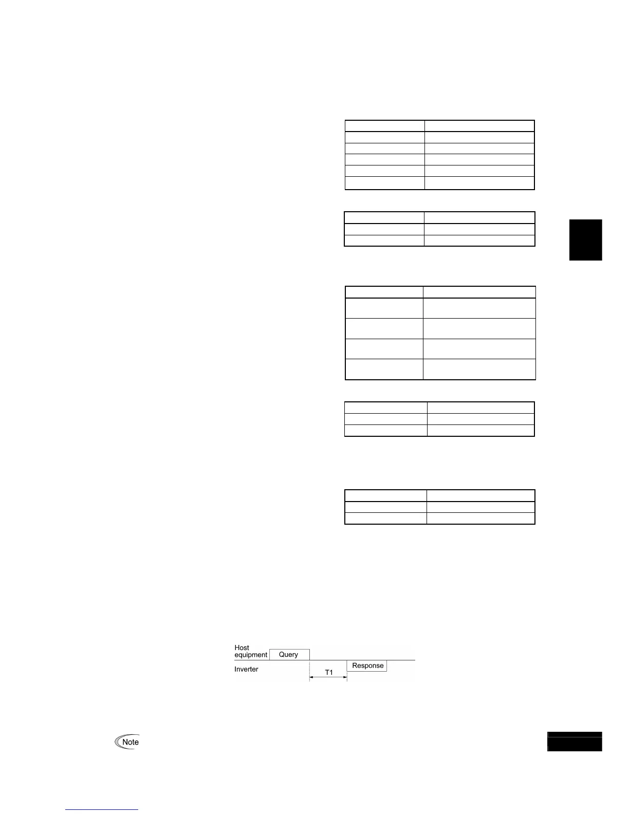
Response interval (y09 for port 1 and y19 for port 2) Data setting range: 0.00 to 1.00 (s)
y09 or y19 specifies the latency time after the end of receiving a query sent from the host equipment (such as a
computer or PLC) until the start of sending the response. This function allows using equipment whose response time is
slow while a network requires quick response, enabling the inverter to send a response timely by the latency time
setting.
T1 = Response interval + α
where α is the processing time inside the inverter. This time may vary depending on the processing status and the
command processed in the inverter.
For details, refer to the RS-485 Communication User's Manual.
When setting the inverter with FRENIC Loader via the RS-485 communications link, pay sufficient attention
to the performance and/or configuration of the PC and protocol converter such as RS-485−RS-232C converter.
Note that some protocol converters monitor the communications status and switch the sending/receiving o
 Loading...


