5-149
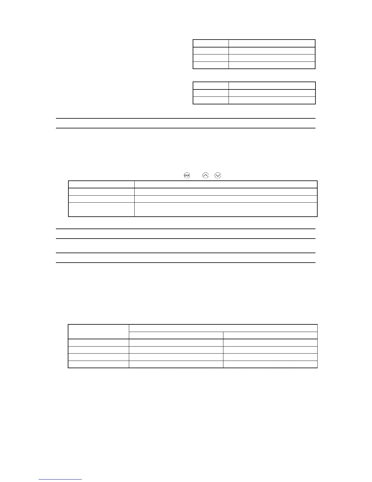
Protocol selection (y10 for port 1)
Data for y10 Protocol
0 Modbus RTU protocol
1 FRENIC Loader protocol
y10 specifies the communications protocol for port 1.
For FRENIC Loader (via the RS-485 communications
link), only y10 can be used for protocol selection. Set the
y10 data at "1."
2 Fuji general-purpose inverter protocol
Protocol selection (y20 for port 2)
Data for y20 Protocol
0 Modbus RTU protocol
y20 specifies the communications protocol for port 2.
2 Fuji general-purpose inverter protocol
y97 Communication Data Storage Selection
A nonvolatile storage in the inverter has a limited number of rewritable times (100,000 to 1,000,000 times). Saving data
into the storage so many times unnecessarily will no longer allow the storage to save data, causing memory errors.
For frequent data writing via the communications link, therefore, a temporary storage is provided instead of the
nonvolatile storage. To use the temporary storage, set the y97 data at "1." Using the temporary storage reduces the
number of data writing times into the nonvolatile storage, preventing memory errors.
Setting the y97 data at "2" saves all data written in the temporary storage into the nonvolatile one.
Changing the y97 data requires simultaneous keying of
and
/
keys.
Data for y97 Function
0 Save into nonvolatile storage (Rewritable times limited)
1 Write into temporary storage (Rewritable times unlimited)
2
Save all data from temporary storage to nonvolatile one
(After saving data, the data automatically returns to "1.")
y98 Bus Link Function (Mode selection) (Refer to H30.)
y99 Loader Link Function (Mode selection)
This is a link switching function for FRENIC Loader. Rewriting the data of y99 to enable RS-485 communications
from Loader helps Loader send the inverter the frequency and/or run commands. Since the data to be set in the function
code of the inverter is automatically set by Loader, no keypad operation is required.
While Loader is selected as the source of the run command, if the computer runs out of control and cannot be stopped
by a stop command sent from Loader, disconnect the RS-485 communications cable from the port 1 or the USB cable,
connect a keypad instead, and reset the y99 data to "0." This setting "0" in y99 means that the run and frequency
command source specified by function code H30 takes place instead of FRENIC Loader.
Note that the inverter cannot save the setting of y99. When power is turned off, the data in y99 is lost (y99 is reset to
"0").
Function
Data for y99
Frequency command Run command
0 Follow H30 and y98 data Follow H30 and y98 data
1 Via RS-485 link (FRENIC Loader) Follow H30 and y98 data
2 Follow H30 and y98 data Via RS-485 link (FRENIC Loader)
3 Via RS-485 link (FRENIC Loader) Via RS-485 link (FRENIC Loader)

 Loading...


