vi
Conformity to the Low Voltage Directive in the EU (Continued)
3. When used with the inverter, a molded case circuit breaker (MCCB), residual-current-operated protective device
(RCD)/earth leakage circuit breaker (ELCB) or magnetic contactor (MC) should conform to the EN or IEC standards.
4. When you use a residual-current-operated protective device (RCD)/earth leakage circuit breaker (ELCB) for protection
from electric shock in direct or indirect contact power lines or nodes, be sure to install type B of RCD/ELCB on the input
(primary) of the inverter if the power supply is three-phase 200/400 V.
5. The inverter should be used in an environment that does not exceed Pollution Degree 2 requirements. If the environment
conforms to Pollution Degree 3 or 4, install the inverter in an enclosure of IP54 or higher.
6. Install the inverter, AC or DC reactor, input or output filter in an enclosure with minimum degree of protection of IP2X
(Top surface of enclosure shall be minimum IP4X when it can be easily accessed), to prevent human body from touching
directly to live parts of these equipment.
7. Do not connect any copper wire directly to grounding terminals. Use crimp terminals with tin or equivalent plating to
connect them.
8. When you use an inverter at an altitude of more than 2000 m, you should apply basic insulation for the control circuits of
the inverter. The inverter cannot be used at altitudes of more than 3000 m.
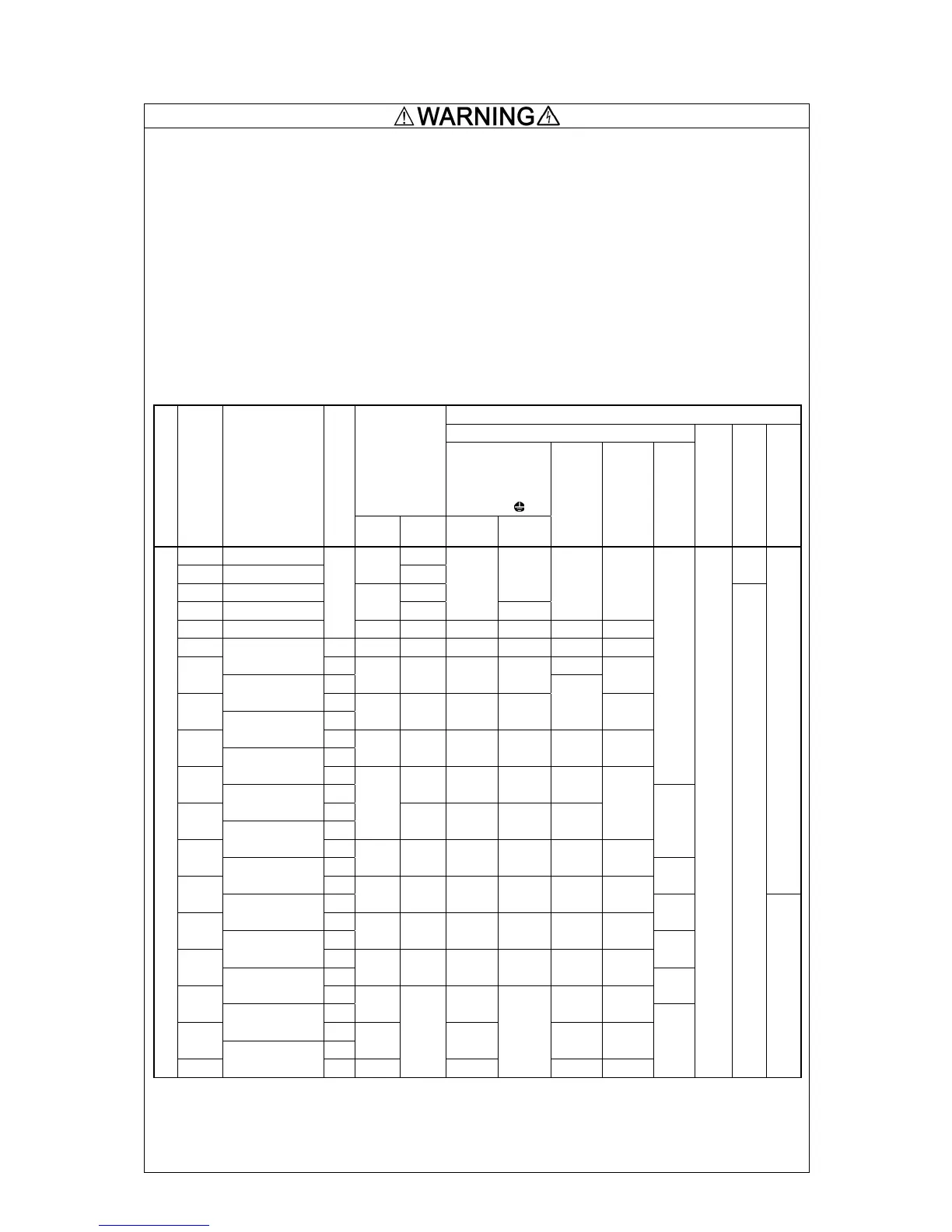
9. Use wires listed in EN60204 Appendix C.
Recommended wire size (mm
2
)
Main circuit
MCCB or
RCD/ELCB *1
Rated current
Main power
input *2
[L1/R, L2/S, L3/T]
Inverter’s
grounding [
G]
Power supply voltage
Nominal applied motor
Inverter type
HD/LD mode
W/
DCR
W/o
DCR
W/
DCR
W/o
DCR
Inverter outputs
[U, V, W] *2
DC reactor
[P1, P(+)] *2
Braking resistor
[P(+), DB] *2
Control circuit
Aux. control power
supply [R0, T0]
Aux. fan power
supply [R1, T1]
0.4 FRN0.4G1
-2 5
0.75 FRN0.75G1
-2
5
10
-
1.5 FRN1.5G1
-2 15
1
2.2 FRN2.2G1
-2
10
20
1
1.5
1 1
3.7 FRN3.7G1
-2
HD
20 30 2.5 4 2.5 2.5
5.5 HD 30 50 4 6 4 4
FRN5.5G1
-2
LD 6
7.5
HD
40 75 6 10 6
FRN7.5G1
-2
LD
11
HD
50 100 10 16
10
16
FRN11G1
-2
LD
15
HD
75 125 16 25 16 25
FRN15G1
-2
LD
1
18.5
HD
150 25 35 25
FRN18.5G1
-2
LD
22
HD
100
175 35 50 35
35
FRN22G1
-2
LD
1.5
30
HD
150 200 50 70 50 70
FRN30G1
-2
LD
2.5
-
37
HD
175 250 70 95 70 95
FRN37G1
-2
LD
4
45
HD
200 300 95 70×2 95 50×2
FRN45G1
-2
LD
6
55
HD
250 350 50×2 95×2 70×2 70×2
FRN55G1
-2
LD
10
75
HD
350 95×2 95×2 95×2
FRN75G1
-2
LD
90
HD
400 120×2 120×2 120×2
Three--phase 200 V
110
FRN90G1
-2
LD 500
-
150×2
-
150×2 150×2
-
0.65
to
0.82
2.5
2.5
Note: A box (
) in the above table replaces S or E depending on the enclosure.
A box () in the above table replaces A or E depending on the shipping destination.
*1 The frame size and model of the MCCB or RCD/ELCB (with overcurrent protection) will vary, depending on the power transformer capacity.
Refer to the related technical documentation for details.
*2 The recommended wire size for main circuits is for the 70°C 600 V PVC wires used at a surrounding temperature of 40°C.