Revision 1 144 9/10/2019
d) Remove the tape cover from the left side of the chassis to view the tape enclosure.
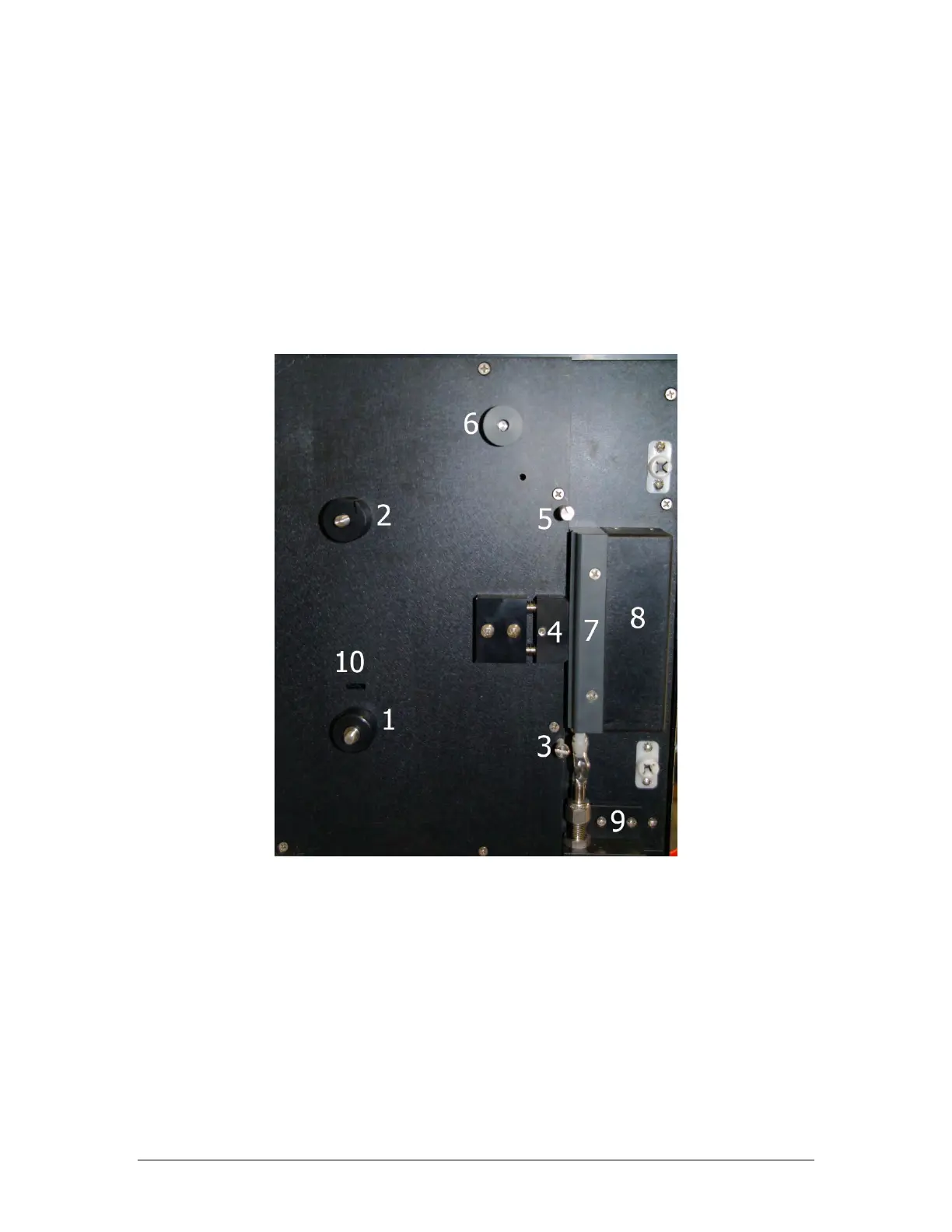
Figure 7-2 presents the open enclosure with various components identified.
e) Remove the screw-on disks (not shown) from the supply reel (1) and take-up reel (2).
f) Take a new reel of tape and remove the adhesive tape securing the end. Place the tape
reel on the supply reel. Make sure the tape is installed so that the loose end hangs down
on the left side of the reel, not the right.
g) Thread the tape over the lower sample chamber guide pin (3). Push the compression
head (4) back and slide the tape behind the compression head. Ensure that the tape is
flat against the groove in the sample chamber (8) and has no creases.
Figure 7-2: Tape Enclosure Parts Reference
h) Pull the tape up over the upper sample chamber guide pin (5).
i) Thread the tape over the black aluminium / grey plastic capstan of the pulse counter (6).
(Note that this capstan may be either aluminium or plastic).
j) Fold over the first inch of the tape, and then slide this folded end of the tape into the slot
on the take-up reel (2), as shown in Figure 7-3.