Q.series
Gantner Instruments GmbH
117
5 Configuration → Configuring analog outputs
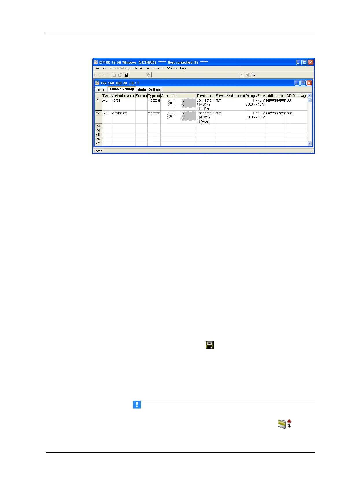
Fig. 5-9 Dialog with configuration for analog outputs.
Procedure 1. Click in the column Type of the first row (V1 = Variable 1) or
mark the row (click on V1) and use Variable definition >
Type.
2. Select Analog. Output.
The column Wiring diagram show
s you the pin assignment.
With more than one output the first outputs are also always
occupied first (first Plug 1, then Plug 2, etc.). Check for cor-
rect connection.
3. Click in the column Variable name and allocate
a name iden-
tifying the signal.
4. Click in the column Type of an
d specify whether you want to
use the output as a Voltage or a Current output.
5. In the Form
at/balance column the output format is shown
which has no further significance here.
6. Click in the column Range/erro
r to define the output scaling
and the reaction in the case of an error (optional).
7. Click in the column Other to specify the signal source (v
ari-
able) used for the output.
8. Save the changes in a file and close the module once you have
made
all the changes:
or File > Save to file and finish.
The file is created within the project folder and the file name
is generated automaticall
y. The project folder bears the same
name as the project. The generated file name contains the
address of the Test Controller through which the module is
connected and an identifier for the relevant module.
If the modules are connected through a Test Controller, new
module settings must also be updated there. Select
or File

 Loading...