Vers. No. 6.1
18 Released: 25/04/2017
3 Introduction
You can insert the Q.gate Test Controller alternatively into the
base to the left or right of the Q.bloxx modules (first or last base).
Since the Q.gate Test Controller has a bus termination, it must be
located on the end of the line and must not be positioned between
the modules.
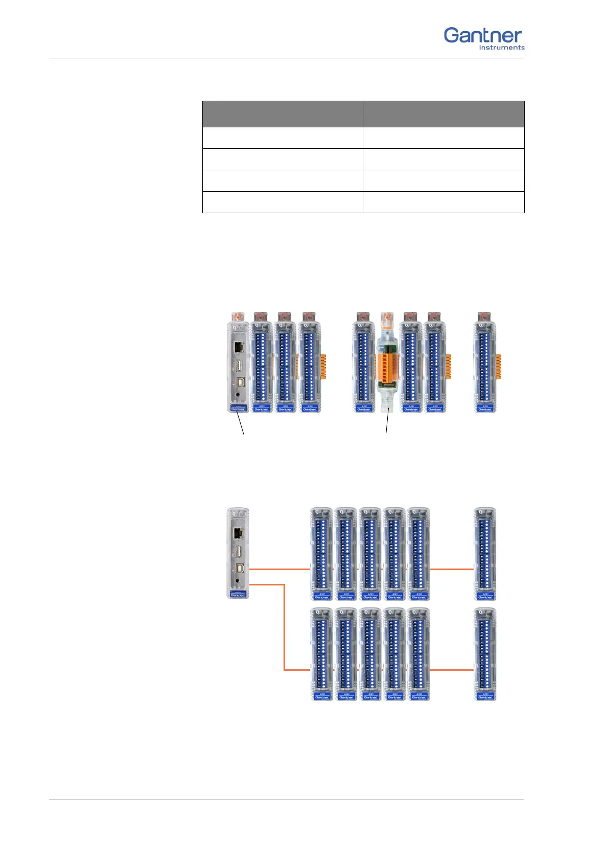
Fig. 3-1 Q.gate with up to 32 modules, connection via base and
Q.bloxx Extension Socket QES.
Fig. 3-2 Q.gate with up to 32 modules, connection via cables.
Cable length in meters Maximum baud rate
1000 < 500 kBaud
100 < 1500 kBaud
20 < 6000 kBaud
10 >6 to 24 MBaud
…
…
max. 16 modulesmax. 16 modules
Extension Socket QES
Q.gate

 Loading...