Q.series
Gantner Instruments GmbH
99
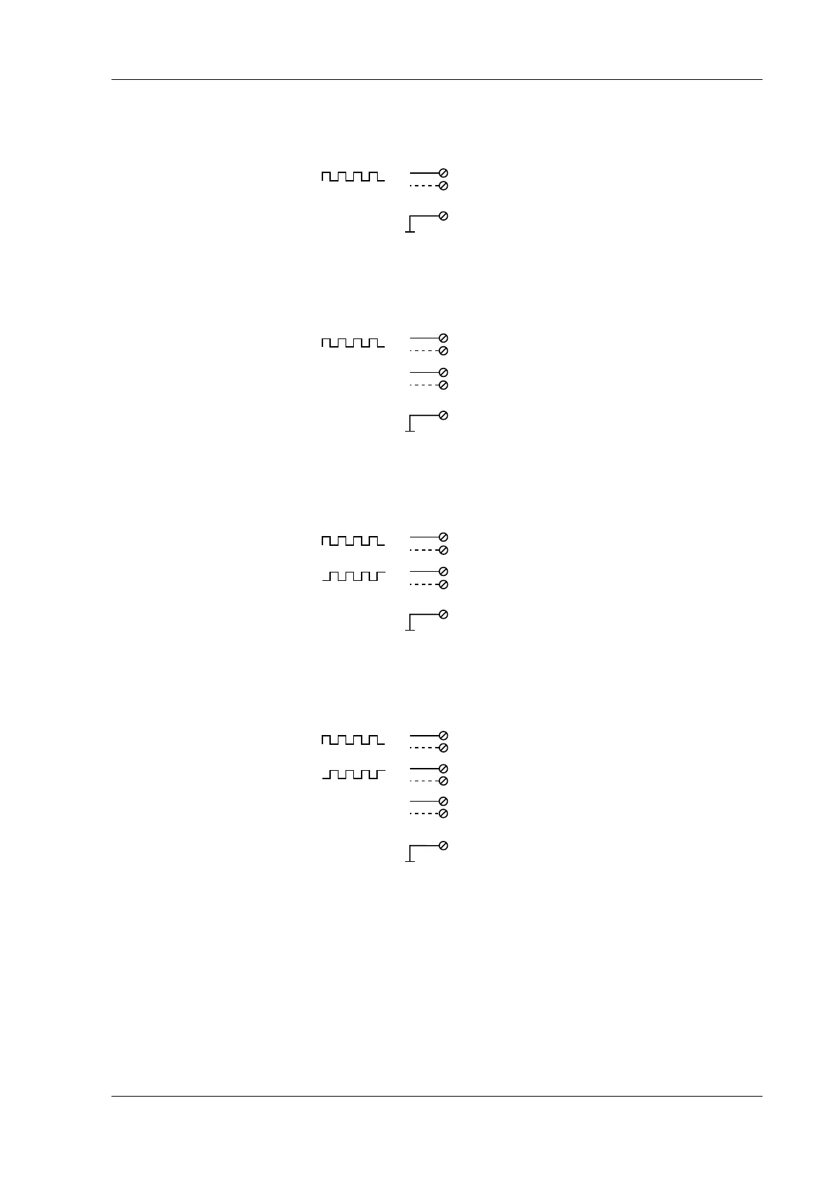
4 Connecting the modules → Q.bloxx D107: Connecting digital inputs
Fig. 4-97 D107, sensor with one signal, single-ended or differential
(input broken line).
Fig. 4-98 D107, sensor with two signals (counting direction), sin-
gle-ended or differential (input broken
line).
Fig. 4-99 D107, sensor with two signals (90° offset), single-ended
or differential (input broken line).
Fig. 4-100 D107, sensor with three signals (2 x 90° offset and zero
reference), single-ended or differential (input broken
line).
D
in
D
in
+/-
D
in
2, 5
3, 6
10 (GND, 0V)
5, 8
6, 9
D
in
0-Ref.
 Loading...
