190-01115-01 G3X™/G3X Touch™ Avionics Installation Manual
Rev. AV Page B-12
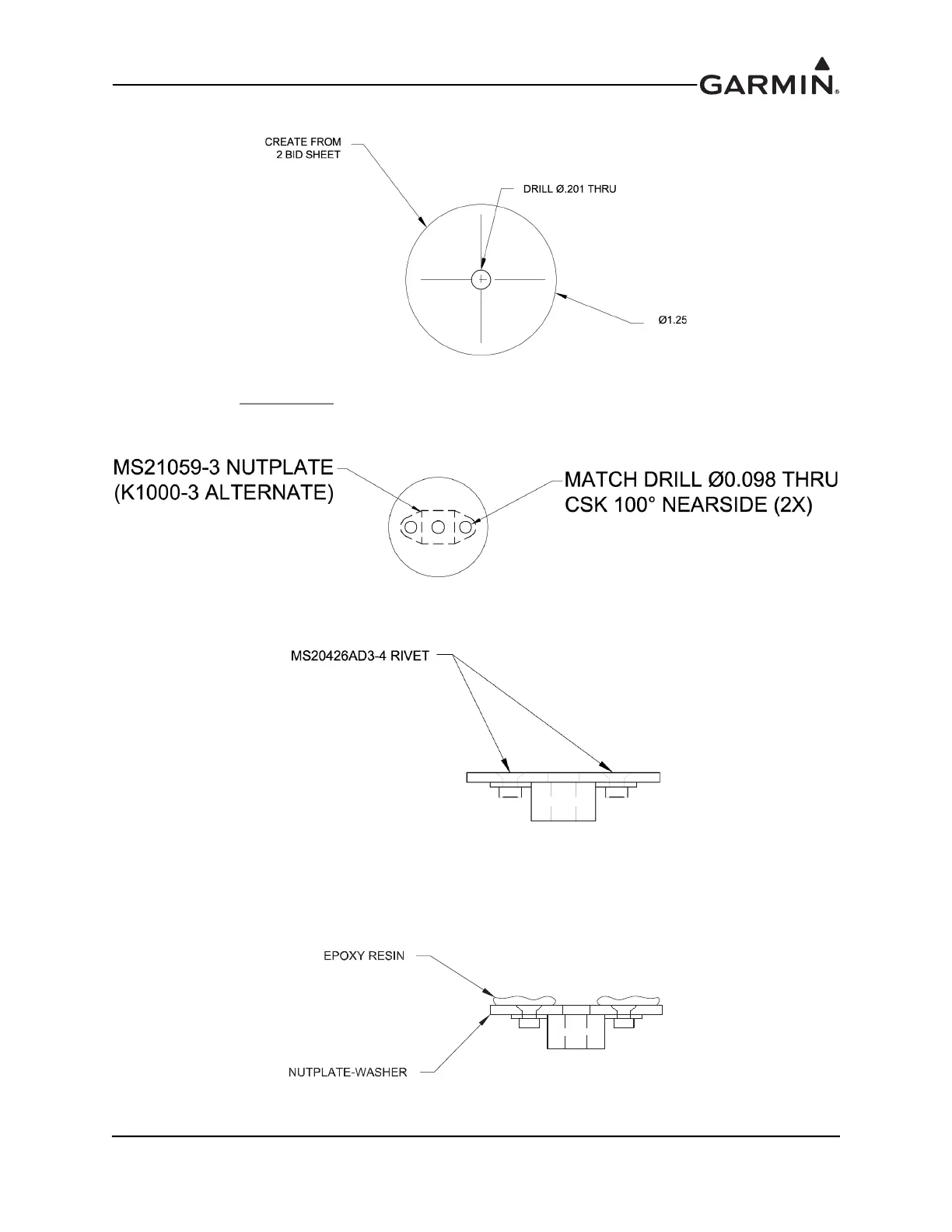
9. Fabricate two disks from 2 BID sheet to the dimensions shown in Figure B-14.
Figure B-14 2 BID Sheet Disk
10. Align one stainless steel
nut plate MS21048-3 (or K1001-3) to each disk using the center hole as a
guide. Match drill 0.098 holes to nut plate and countersink 100° on one side. Refer to
Figure B-15.
Figure B-15 Aligned Nut Plate And Disk
11. Rivet nut plate to disk with MS20426AD3-4 rivets as shown in Figure B-16.
Figure B-16 Riveted Nut Plate And Disk
12. Place the Magnetometer Mounting Assembly aft of the spare and level with the typical flight atti-
tude. Make sure there is sufficient head room for the pig tail to bend clear of the wing tip.
13. Match drill the Magnetometer Bracket to the wing rib.
14. Apply epoxy resin to the flat side of the nut plate washers, see Figure B-17.
Figure B-17 Nut Plate Washers
 Loading...


