190-01115-01 G3X™/G3X Touch™ Avionics Installation Manual
Rev. AV Page B-15
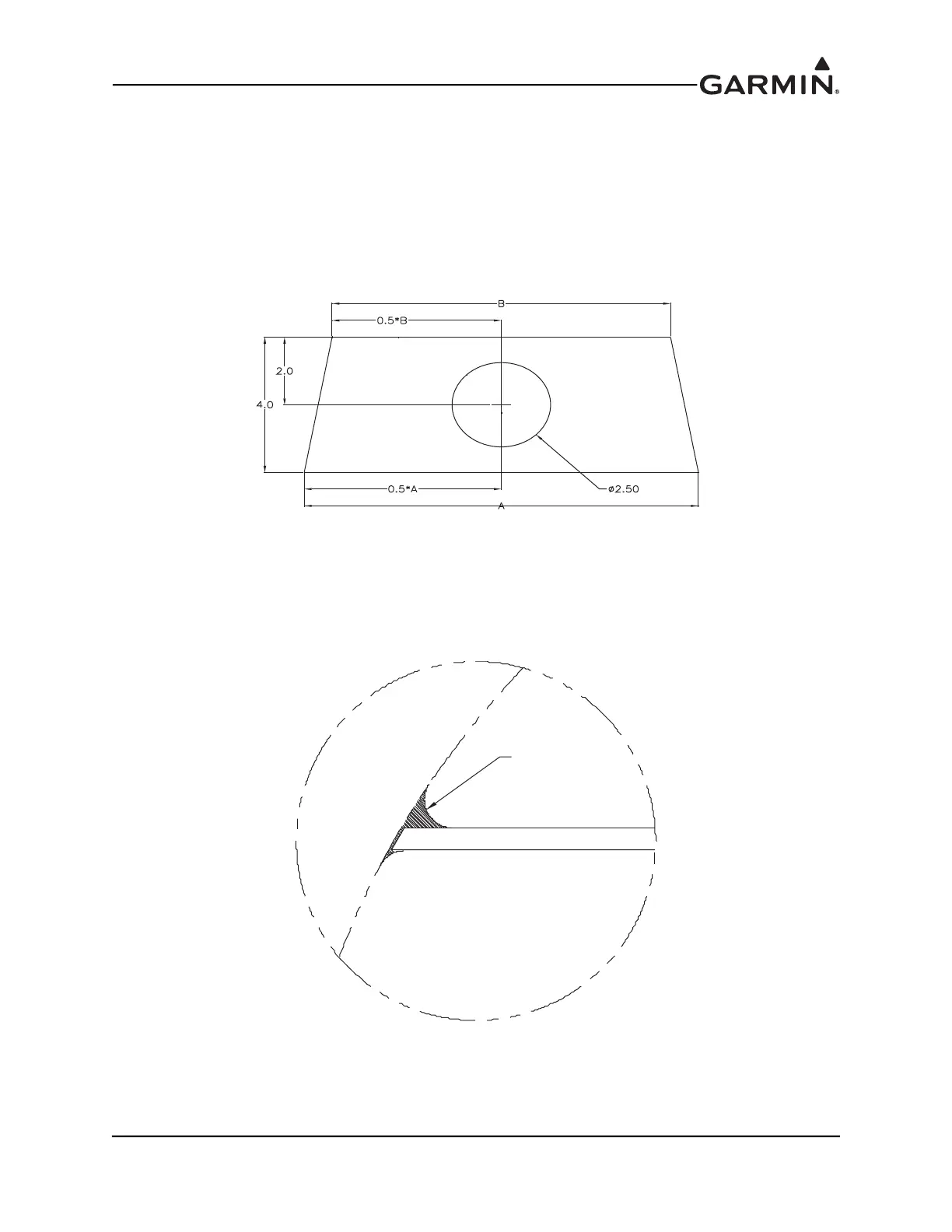
3. Measure the fuselage in multiple locations to find the size of the shelf. The shelf will have an
approximate trapezoidal shape and should have a depth of at least 4.0 in. Cut the shelf from 0.25
in. thick, 2-ply per side prepreg. Cut a 2.50 in. diameter hole in the center of the shelf, as shown in
Figure B-21. Alternately, the 2.50 in. diameter hole can move left or right on the shelf, so long as
there is adequate clearance to install or remove the magnetometer. By placing the hole in the center
of the shelf, the elevator control tube can be used more effectively in a later step to align the GMU
22 Installation Rack with the aircraft’s forward direction. Prepare for shelf installation by sanding,
roughing up, and cleaning all bonding areas on the shelf and fuselage for best adhesion.
Figure B-21 Example Magnetometer Shelf
4. Fill gap between sides of fuselage and shelf with epoxy/flox mixture. Be sure to make a radius at
the corners as shown in Figure B-22 to smooth the corners for laying glass in the following steps.
When aligning the shelf, make sure the shelf remains level to within 3° of the pitch and roll axes.
Figure B-22 Fill Detail For Corner Radii And Magnetometer Shelf
FILL WITH
EPOXY/FLOX
MIXTURE